Automatic alignment system of inclined contact type laser gyro

A laser gyroscope and contact technology, which can be used in closed-circuit television systems, Sagnac effect gyroscopes, and the method of comparing with reference electrical parameters. and other problems, to achieve the effect of accurate loss value, precise positioning, and reduction of human error

Inactive Publication Date: 2011-08-31
HARBIN INST OF TECH
View PDF1 Cites 4 Cited by
  • Summary
  • Abstract
  • Description
  • Claims
  • Application Information

AI Technical Summary

Problems solved by technology

[0003] In order to solve the problem that the existing method cannot accurately adjust the cavity, and the cumbersome operation process, low sampling rate and spectrum curve distortion existing in the measurement of the oscilloscope, the present invention proposes an inclined contact laser gyroscope automatic cavity adjustment system

Method used


Image

  • Automatic alignment system of inclined contact type laser gyro
  • Automatic alignment system of inclined contact type laser gyro
  • Automatic alignment system of inclined contact type laser gyro

Examples


specific Embodiment approach 1

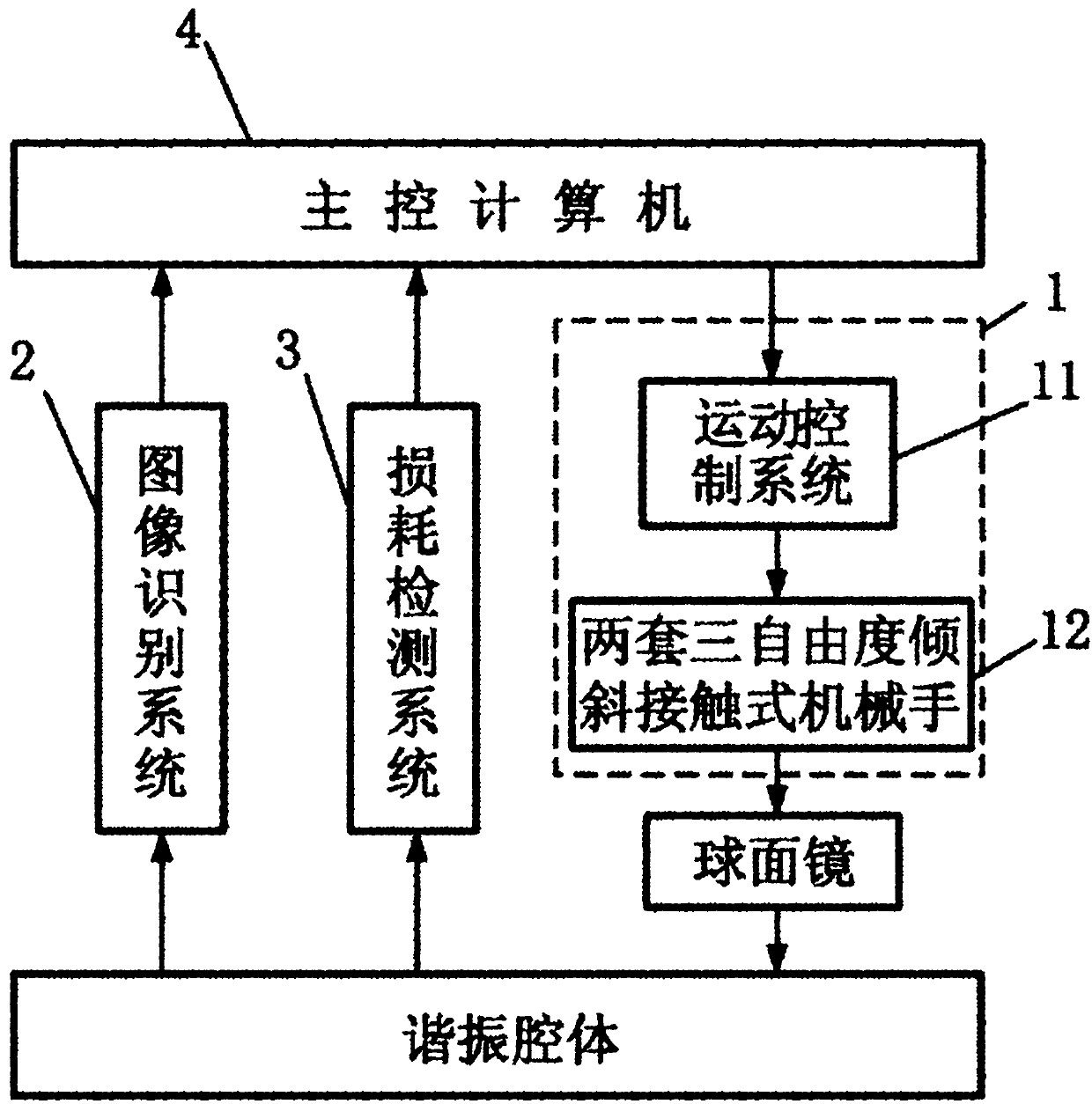
[0012] Specific implementation mode one: combine Figure 1 to Figure 7 Describe the present embodiment, the inclined contact laser gyro automatic cavity adjustment system in this embodiment is used to adjust the positions of the two station spherical mirrors on the optical glue surface of the resonant cavity;

[0013] It consists of an inclined contact cavity adjustment mechanism and its control system 1, image recognition system 2, loss detection system 3 and main control computer 4;

[0014] Inclined contact cavity adjustment mechanism and its control system 1 are composed of a motion control system 11 and two sets of three-degree-of-freedom inclined-contact manipulators 12. The two sets of three-degree-of-freedom inclined-contact manipulators 12 have the same structure and are respectively used for resonant cavity Adjustment of the two-station spherical mirrors on the body;

[0015] The image recognition system 2 is used to capture the aperture of the resonant cavity and t...

specific Embodiment approach 2

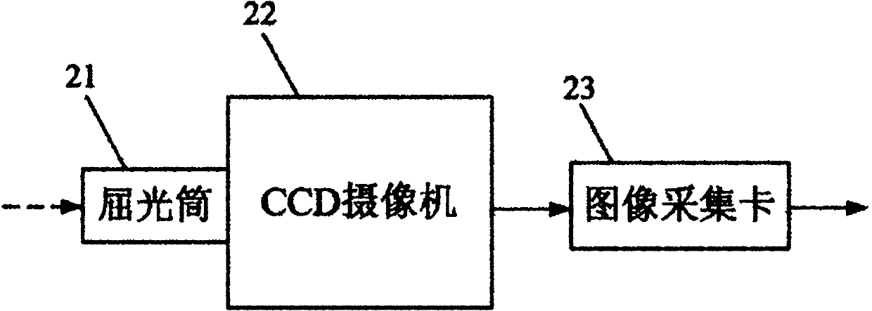
[0020] Specific implementation mode two: combination figure 2 Describe this embodiment, the difference between this embodiment and the specific embodiment is that the image recognition system 2 is made up of a diopter 21, a CCD camera 22 and an image acquisition card 23, and the lens on the CCD camera 22 is equipped with a diopter 21, The output beam of the resonant cavity is incident into the lens of the CCD camera 22 through the diopter 21, the image signal output end of the CCD camera 22 is connected to the image signal input end of the image acquisition card 23, and the image data output end of the image acquisition card 23 is connected to the main The image data input terminal of the control computer 4. Other compositions and connection methods are the same as those in Embodiment 1.

specific Embodiment approach 3

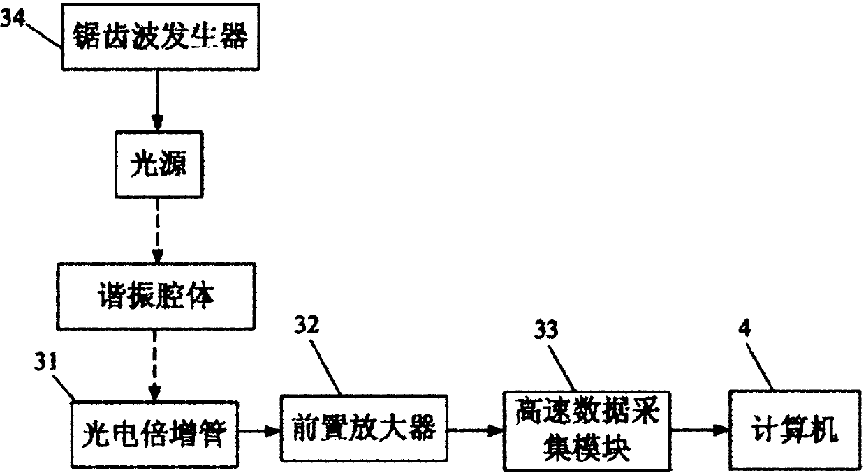
[0021] Specific implementation mode three: combination image 3 Describe this embodiment, the difference between this embodiment and the specific embodiment one or two is that the loss detection system 3 is composed of a photomultiplier tube 31, a preamplifier 32, a high-speed data acquisition module 33 and a sawtooth wave generator 34, and the sawtooth wave generator 34 drives the light source to generate reference light, the reference light is light that is periodically scanned within a certain frequency range, the reference light is incident into the resonant cavity, and forms a stable oscillation in the cavity, and the collection end of the photomultiplier tube 31 collects The output light of the resonant cavity, and the output light is amplified and converted into an electrical signal and then output to the preamplifier 32, the preamplifier 32 outputs the signal to the high-speed data acquisition module 33, and the high-speed data acquisition module 33 outputs the signal t...


PUM


Abstract

The invention discloses an automatic alignment system of an inclined contact type laser gyro, and relates to the field of automatic control. The automatic alignment system solves the problem that a current method can not accurately align as well as the defects of fussy operating process, lower sampling speed and spectrum curve distortion caused by using an oscillograph to measure. The speckle images of diaphragms and output lights are captured by an image recognition system; the output lights are acquired by a loss detecting system and are converted into electrical signals; the captured images are processed by a master computer to obtain the coordinates of the central points of the speckles and the diaphragms, calculate and obtain the deviations of the positions of the speckles and the diaphragms and use the deviations as coarse adjusting parameters; then the electrical signals are processed to draw a frequency spectrum scattergram; and the loss value is calculated and used as fine adjusting parameters; an inclined contact type alignment system and the control system thereof consist of a movement control system and two sets of three-degree of freedom inclined contact manipulators with the same structure; the positions of an upper station spherical mirror and a lower station spherical mirror on a optical cement surface of a resonant cavity are adjusted according to the parameters received by the control system; and therefore, automatic alignment is realized.

Description

technical field [0001] The invention relates to the field of automatic control. Background technique [0002] Laser gyroscope is an ideal device for strapdown inertial navigation system, especially in the military field, laser gyroscope occupies a pivotal position. Cavity tuning is a difficult point in the manufacturing process of laser gyroscopes. The precision of cavity tuning is not only directly related to whether the resonant cavity can generate laser light, but also directly affects various performance indicators of the laser gyroscope. my country's laser gyro cavity adjustment assembly technology is relatively backward, and manual methods have been mainly used for a long time. Manual tuning requires high operator experience and skills, high labor intensity and low efficiency, and due to uncertain factors such as experience and emotions, the quality of tuning is unstable, which seriously restricts the improvement of product output and quality control. The existing ...

Claims


Application Information

Patent Timeline
Patent Type & Authority Applications(China)
IPC IPC(8): G01C19/64H04N7/18G01J1/16
Inventor 荣伟彬马立何正峰欧阳航空孙立宁
Owner HARBIN INST OF TECH
Why Eureka
Try Eureka