Extrusion equipment with multiple extrusion rods

A technology of extrusion equipment and extrusion rod, which is used in metal extrusion, indenter/punch rod, metal processing equipment, etc. The effect of low production cost and good production performance

Inactive Publication Date: 2011-09-07
尚守亮 +1
View PDF5 Cites 15 Cited by
  • Summary
  • Abstract
  • Description
  • Claims
  • Application Information

AI Technical Summary

Problems solved by technology

Therefore, according to the existing extrusion cylinder and extrus

Method used


Image

  • Extrusion equipment with multiple extrusion rods
  • Extrusion equipment with multiple extrusion rods
  • Extrusion equipment with multiple extrusion rods

Examples


Embodiment 1

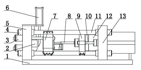
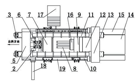
[0034] like figure 1 , 2 , 3, 4, 8, 9, 10, and 11, a multi-extrusion rod 8 extrusion equipment, which includes a main cylinder 14, an auxiliary cylinder 15, a rear beam 13, a main plunger 12, an auxiliary plunger 10, a front Beam 5, column 11, slide rail 19, clamping cylinder 3, base 1 and lock nut 4, main cylinder 14 and auxiliary cylinder 15 are fixed on the back beam 13, the front end of main cylinder 14 is provided with main plunger 12, auxiliary cylinder The front end of 15 is provided with an auxiliary plunger 10, the front beam 5 and the rear beam 13 are connected by a column 11, the column 11 and the front and rear beams 13 are all fixed by lock nuts 4, the front beam 5 and the rear beam 13 are fixed on the machine base 1, and the column 11 is provided with a slide rail 19 and a feeding trolley 17, and the front beam 5 is provided with a clamping cylinder 3, an extrusion mold base 2, a scissors cylinder 6 and a mold changing cylinder 18, and an extrusion mold is arran...

Embodiment 2

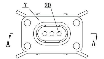
[0039] like Figure 5 As shown, Example 1 is repeated, with the following differences. The extrusion cylinder 7 is a cylindrical extrusion cylinder 7, and three extrusion holes 20 are arranged in the extrusion cylinder 7, and the extrusion holes 20 are arranged in a straight line. In this embodiment, the maximum width of the extruded hollow profile is: B=(3 root square root)*1.3*D=2.25D, where D is the diameter of the extrusion hole when extruding with a single extrusion hole.

Embodiment 3

[0041] like Figure 12 Shown, repeat embodiment one, following difference is arranged, and described extruding die is split flow die, promptly die bridge 26 is set in the middle of upper die 23 and lower die 24, and die bridge 26 connects upper die 23 and lower die 24 The metal runner is divided into two parts.


PUM


Abstract

The invention relates to extrusion equipment with multiple extrusion rods. In the extrusion equipment, an extrusion rod holder is arranged on a movable cross beam, at least two extrusion rods are arranged on the extrusion rod holder, and extrusion holes in the same number as the extrusion rods are formed at positions corresponding to positions of the extrusion rods; an extrusion die corresponds to an extrusion cylinder, the extrusion die comprises a deflector, an upper die and a lower die, which are connected in turn, deflecting grooves in the same number as the extrusion holes are formed in the deflector, the outlets of the deflecting grooves are communicated with each other, the inlets of the deflecting grooves correspond to the extrusion holes, and the deflecting grooves are communicated with the upper and lower dies. The plurality of extrusion holes are formed in the extrusion cylinder, the extrusion rods correspond to the extrusion holes are arranged, the deflector is arranged on the extrusion die, the extrusion rods extrude a metal extrusion blank material out from the plurality of extrusion holes, the extruded blank material is deflected by the deflector into the die, and thus, an extruder can produce metal sections, which are wider than those made by the conventional extrusion equipment of the same tonnage, particularly wide aluminum and magnesium alloy thin-wall hollow sections.

Description

Technical field: [0001] The invention belongs to the technical field of metal profile preparation tools, and in particular relates to a multi-extrusion rod extrusion equipment suitable for preparing wide-width hollow thin-wall profiles. Background technique: [0002] Large-scale aluminum and magnesium alloy profiles, especially wide hollow thin-walled profiles, have good application prospects in the manufacture of aerospace vehicles, transportation equipment, especially modern rail transportation equipment. [0003] Existing methods for preparing aluminum and magnesium alloy profiles are extrusion methods, in which aluminum and magnesium alloy ingots are extruded into aluminum and magnesium alloy profiles through extrusion equipment and extrusion tools. When extruding aluminum and magnesium alloy profiles, the width of the formed aluminum and magnesium alloy profiles is restricted by the diameter of the billet; the diameter of the billet is limited by the diameter of the ext...

Claims


Application Information

Patent Timeline
IPC IPC(8): B21C23/21B21C27/00B21C26/00B21C25/02
Inventor 尚守亮霍天常潘复生彭建
Owner 尚守亮
Why Eureka
Try Eureka