Laser imaging device and method with unequal distances

A laser imaging and spacing technology, which is applied in photoelectric typesetting devices, phototypesetting devices, printing, etc., can solve the problem of inflexible typesetting design

Inactive Publication Date: 2014-03-05
北京华源集智科技有限公司
View PDF5 Cites 0 Cited by
  • Summary
  • Abstract
  • Description
  • Claims
  • Application Information

AI Technical Summary

Problems solved by technology

[0003]At present, the most widely used chip spacing is either equidistant, or two different spacings at the same time, although such a geometric design can meet the most effective spiral printing Requirements, but with certain limitations, the typesetting design is not flexible enough

Method used


Image

  • Laser imaging device and method with unequal distances
  • Laser imaging device and method with unequal distances
  • Laser imaging device and method with unequal distances

Examples


Embodiment 1

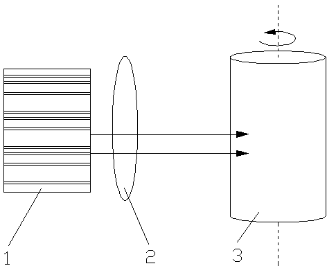
[0022] Refer to attached figure 1 The shown laser imaging device with unequal spacing includes a laser chip 1 that emits a plurality of parallel and spaced laser arrays, an optical element 2 that focuses the light beams, a printed substrate on which the laser arrays are imaged, and drives The drum 3 on which the printed substrate rotates.

[0023] The optical element 2 in this embodiment is a micro-optical lens array, and the printed substrate is a heat-sensitive stencil that can be sensitive to laser light or generate heat by absorbing laser energy.

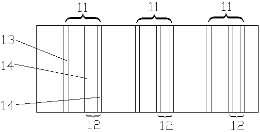
[0024] Refer to attached figure 2 The laser array emitted by the shown laser chip 1 includes a plurality of laser groups 11 spaced apart from each other, and the distance between every two adjacent laser groups 11 is a first distance, and each laser group 11 includes a first Laser 13 and laser group 12, the spacing between the first laser 13 and the laser group 12 is the second spacing, the second spacing is not equal ...

Embodiment 2

[0031] The components of the laser imaging device with unequal pitches in this embodiment are basically the same as those in the first embodiment above, except that the laser arrays emitted by the laser chip 1 have different pitches.

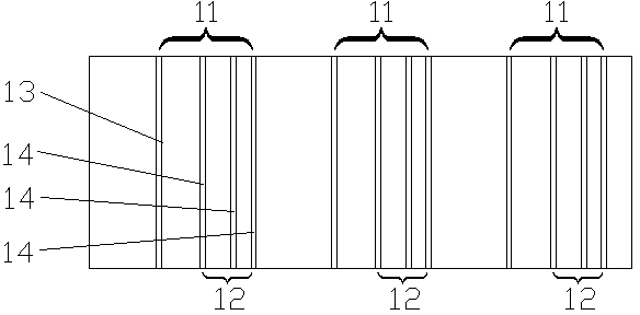
[0032] Refer to attached image 3 , the laser array includes a plurality of laser groups 11 spaced apart from each other, the spacing between every two adjacent laser groups 11 is a first pitch, each laser group 11 includes a first laser 13 and a laser group 12, the first laser 13 The spacing between the laser group 12 is the second spacing, and the second spacing is not equal to the first spacing. Each laser group 12 includes at least two second laser beams 14, and the adjacent second lasers in each laser group 12 The distance between 14 is not equal to the second distance and the first distance respectively. In this embodiment, there are more than 2 second laser beams 14 in the laser group 12, and there are 3 beams, and the distance betwe...


PUM


Abstract

The invention discloses a laser imaging device with unequal distances, comprising a laser chip, an optical element, a printing substrate and a rotary drum, wherein the laser chip emits a plurality of laser arrays which are parallel to each other and are at intervals with each other, the optical element is used for focusing a light beam, the laser array is imaged on the printing substrate, the rotary drum is used for driving the printing substrate to rotate, each laser array comprises a plurality of laser groups which are arranged at intervals with each other, a distance between every two adjacent laser groups is a first distance, each laser group comprises a first laser and a laser sub-group, a distance between the first laser and the laser sub-group is a second distance, the first distance is unequal to the second distance, each laser sub-group comprises at least two beams of second lasers, and the distance between the adjacent second lasers in each laser sub-group is not equal to the second distance and the first distance, respectively. By adopting the multi-distance laser array, some additional performances, such as more flexible design can be obtained, the performance can be further optimized, and requirements on different users can be better satisfied.

Description

technical field [0001] The invention relates to a laser imaging device and method with unequal spacing. Background technique [0002] So far, the realization of computer plate-making printing with semiconductor laser arrays has been very mature. The semiconductor laser chip used for computer plate-making and printing has many important parameters, including laser wavelength, power, linearity of power-current characteristics, near-field and far-field size. In addition, from a geometric point of view, there are two important parameters, one is the number of lasers on the chip, and the other is the distance between lasers. [0003] At present, the most widely used chip spacing is either equidistant or two different spacings at the same time. Although this geometric design can meet the most effective spiral printing requirements, it has certain limitations and is not flexible enough in layout design. Contents of the invention [0004] In order to overcome the above di...

Claims


Application Information

Patent Timeline
Patent Type & Authority Patents(China)
IPC IPC(8): B41C1/05B41B19/00B41B21/16
Inventor 根林·谈
Owner 北京华源集智科技有限公司
Why Eureka
Try Eureka