Low-emission combustion chamber with main combustible stage head part multi-point slant oil taking

A main combustion stage and combustion chamber technology, applied in the combustion chamber, continuous combustion chamber, combustion method, etc., to achieve the effects of reduced size, simple structure and easy assembly

Active Publication Date: 2013-03-06
BEIHANG UNIV
View PDF0 Cites 2 Cited by
  • Summary
  • Abstract
  • Description
  • Claims
  • Application Information

AI Technical Summary

Problems solved by technology

[0008] The technical problem to be solved by the present invention is: to overcome the deficiencies of the existing technology, and use premixed combustion technology to provide a low-emission combustion chamber with multi-point oblique oil inlet at the head of the main combustion stage, and the oil and gas distribution in the combustion zone of the combustion chamber is even , not only can maintain low pollution emissions under large working conditions, but also can ensure the stable operation of the engine under small working conditions

Method used


Image

  • Low-emission combustion chamber with main combustible stage head part multi-point slant oil taking
  • Low-emission combustion chamber with main combustible stage head part multi-point slant oil taking
  • Low-emission combustion chamber with main combustible stage head part multi-point slant oil taking

Examples


Embodiment Construction

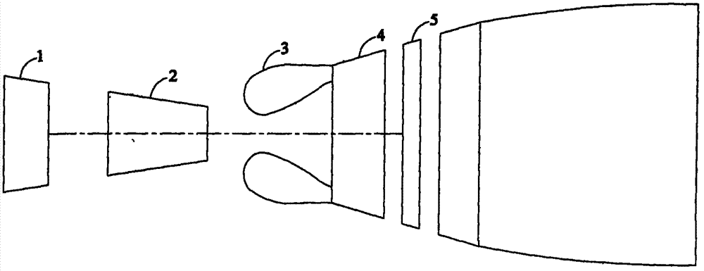
[0034] figure 1 It is a schematic diagram of the engine structure, including a low-pressure compressor 1, a high-pressure compressor 2, a combustion chamber 3, a high-pressure turbine 4 and a low-pressure turbine 5. When the engine is working, the air is compressed by the low-pressure compressor 1 and enters the high-pressure compressor 2. The high-pressure air then enters the combustion chamber 3 to burn with fuel. The high-temperature and high-pressure gas formed after combustion enters the high-pressure turbine 4 and low-pressure turbine 5, and passes through the turbine. Work is done to drive the high-pressure compressor 2 and the low-pressure compressor 1 respectively.

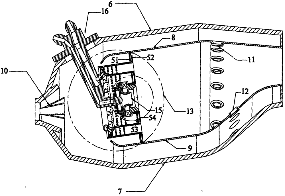
[0035] Such as figure 2 As shown, the combustion chamber 3 adopts a single-annular cavity structure, and the casing 6 outside the combustion chamber and the casing 7 inside the combustion chamber constitute the outer contour of the combustion chamber, and are connected with the high-pressure compressor ...


PUM


Abstract

The invention relates to a low-emission combustion chamber with main combustible stage head part multi-point slant oil taking. A single-ring cavity structure is adopted; the combustion chamber is composed of a combustion chamber outer casing, a combustion chamber inner casing, a flame tube outer wall, a flame tube inner wall and a combustion chamber head part; all the air for combustion enters a flame tube from the combustion chamber head part, a classification combustion scheme is adopted, and is divided into a pre-combustion stage and a primary combustion stage; a diffusion combustion organization mode with stable rotational flow is adopted for the pre-combustion stage, and a premixing combustion organization mode with slant oil supplying is adopted for the main combustible stage; the stable working range of the combustion chamber is mainly controlled by the pre-combustion stage, the stable combustion in the combustion chamber within a wider working range can be ensured, and simultaneously a stable ignition source can be provided for the main combustion stage; and the pollution emission of the combustion chamber is mainly controlled by the main combustion stage, and the equivalent weight ratio of the premixing gas of the main combustion stage is controlled in a low-pollution combustion range, thus the great pollution emission reduction of the whole combustion chamber can be ensured. The premixing and pre-evaporation structure provided by the invention is simple, the favorable combustion stability of the combustion chamber is ensured, and simultaneously the pollution emission is reduced greatly.

Description

technical field [0001] The invention relates to a low-pollution combustion chamber of an aviation gas turbine utilizing premixed combustion technology. The staged combustion mode is adopted, the pre-combustion stage adopts the diffusion combustion organization method, the main combustion stage adopts the pre-mixed combustion organization method, and the main combustion stage adopts multi-point oblique fuel supply at the head. The invention can ensure a wide stable working range of the combustion chamber while reducing the pollution discharge of the combustion chamber. Background technique [0002] The basic performance and structural distribution of modern aero-engine combustors have reached a fairly high level, but there are still a lot of problems and challenges for modern aero-engine combustors. The development and application of new materials, new processes, new structures, and new concepts It is the source to ensure its continuous progress. [0003] The main developme...

Claims


Application Information

Patent Timeline
Patent Type & Authority Patents(China)
IPC IPC(8): F23R3/30F23R3/34
Inventor 付镇柏林宇震许全宏张弛
Owner BEIHANG UNIV
Why Eureka
Try Eureka