Long duration induced voltage withstand test device of ultrahigh-voltage transformer

A technology of withstand voltage test device and step-up transformer, which is applied in testing circuits, testing dielectric strength, etc., can solve the problems of unreasonable parameter configuration, restricting test efficiency, lack of parameter configuration methods, etc., and achieves easy transportation and applicability. Strong, easy-to-manufacture effects

Active Publication Date: 2011-09-07
GANSU ELECTRIC POWER RES INST +1
View PDF2 Cites 24 Cited by
  • Summary
  • Abstract
  • Description
  • Claims
  • Application Information

AI Technical Summary

Problems solved by technology

In the prior art, for the long-term induction withstand voltage test of voltage grade transformers, the parameter configuration of the test equipment is mostly determined according to field experience values, and there is a lack of a set of scientific, reasonable, economical and practical parameter configuration methods
With the rapid development of ultra-high voltage and ult...

Method used


Image

  • Long duration induced voltage withstand test device of ultrahigh-voltage transformer
  • Long duration induced voltage withstand test device of ultrahigh-voltage transformer
  • Long duration induced voltage withstand test device of ultrahigh-voltage transformer

Examples


Embodiment 1

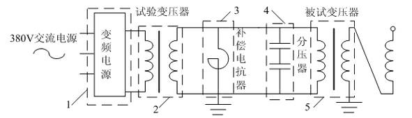
[0019] Example 1, such as figure 1 As shown, the long-term induced withstand voltage test device for ultra-high voltage transformers is characterized in that: the test device includes a test power module 1, a test transformer 2, a test compensation reactor 3 and a voltage divider 4, and the test compensation reactance The device 3 and the voltage divider 4 are arranged in parallel between the test transformer 2 and the tested transformer 5 , and the test power supply module 1 is connected to the test transformer 2 . The test power supply module 1 is a high-power variable frequency power supply. The high-power frequency conversion power supply mainly uses power electronic equipment to rectify the alternating current into direct current, and then converts the direct current into alternating current through the inverter circuit. value.

[0020] The test transformer 2 uses a secondary side multi-tap transformer, the primary side of which is connected to the output of the variabl...

Embodiment 2

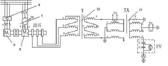
[0021] Example 2, such as figure 2 , the difference from embodiment 1 is that the test power supply module 1 can also be a frequency multiplier power supply composed of two motors, including a three-phase rotor wound asynchronous motor 9 and a three-phase asynchronous squirrel-cage motor 8, a three-phase asynchronous squirrel-cage motor The cage motor 8 is used to drive the three-phase rotor wound asynchronous motor 9, the three-phase asynchronous squirrel cage motor 8 is provided with a starter 6, the three-phase rotor wound asynchronous motor 9 is provided with a voltage regulator 7, and the three-phase rotor The wound asynchronous motor 9 is connected to a first step-up transformer 10 , and the first step-up transformer 10 is connected to a voltage division measurement system 11 . When in use, first start the squirrel cage motor M1 to the rated speed, and then use a three-phase power supply with the opposite phase sequence to the squirrel cage motor, and excite the stator ...

Embodiment 3

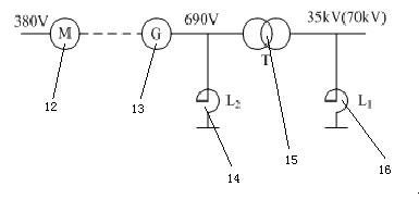
[0022] Example 3, such as image 3 , the difference from embodiment 1 is that the test power module 1 can also be an intermediate frequency brushless excitation synchronous motor unit composed of an asynchronous induction motor 12 and a brushless intermediate frequency synchronous motor 13, and the brushless intermediate frequency synchronous motor 13 and the second booster The transformer 15 is connected, the iron core reactor 14 is arranged between the brushless intermediate frequency synchronous motor 13 and the second step-up transformer 15 , and the air-core reactor body 16 is connected with the second step-up transformer 15 . Its working principle is: the intermediate frequency generator sends out single-phase or three-phase AC power with a certain frequency (250Hz), which is boosted by the intermediate transformer, and at the same time, the compensation reactor is used to adjust and compensate the capacitive current of the tested transformer to obtain the required the t...


PUM

PropertyMeasurementUnit
Equivalent capacitanceaaaaaaaaaa

Abstract

The invention relates to the technical field of a long duration induced voltage withstand test device of ultrahigh-voltage and extraordinarily high-voltage transformer, in particular to a long duration induced voltage withstand test device of an ultrahigh-voltage transformer. The long duration induced voltage withstand test device of ultrahigh-voltage transformer is characterized in that the test device includes a test power supply module, a test transformer, a test compensation reactor and a voltage divider; the test compensation reactor and the voltage divider are arranged in parallel between the test transformer and a to-be-tested transformer; and the test power supply module is connected with the test transformer. During the testing, the test device can directly determine the parameters of the compensation reactor desired for the test according to the type of the transformer by configuring the parameters of each part, thereby obviating the process for determining the parameters of the compensation reactor through a plurality of trails in the prior art. By using the symmetrical voltage applying method, the design insulation level of a single test transformer and a single reactor can be reduced. Accordingly, the test device is convenient in manufacture and is easy to transport in comparison to the existing equipment, and is more applicable, scientific, reasonable and economic in comparison to the equipment with high rated voltage.

Description

technical field [0001] The invention relates to the technical field of ultra-high voltage and ultra-high voltage transformer long-duration induction withstand voltage test equipment, in particular to an ultra-high voltage transformer long-duration induction withstand voltage test device. Background technique [0002] At present, the long-term induction withstand voltage test is one of the important items in the on-site handover test of EHV and UHV transformers. This test is an important means to check the quality of transformer transportation, installation and other links, and to ensure its safe and reliable operation. The principle of the test is to use the combination of variable frequency power supply, excitation transformer, reactor and other related equipment to generate test voltage, and apply it to the tested transformer to achieve the purpose of induction withstand voltage. In the prior art, for the long-term induction withstand voltage test of voltage grade transfor...

Claims


Application Information

Patent Timeline
IPC IPC(8): G01R31/12G01R31/14
Inventor 吕景顺马建海温定筠张广东张凯郭光焰朱生鸿蒋臣王多王维洲靳丹
Owner GANSU ELECTRIC POWER RES INST
Why Eureka
Try Eureka