Long duration induction voltage withstand test device of ultrahigh-voltage transformer
A voltage withstand test device and step-up transformer technology, which is applied in the direction of testing circuits and dielectric strength, can solve the problems of restricting test efficiency, unreasonable parameter configuration, lack of parameter configuration methods, etc., and achieve convenient manufacturing and applicability Strong, easy transport effect
- Summary
- Abstract
- Description
- Claims
- Application Information
AI Technical Summary
Problems solved by technology
Method used
Image
Examples
Embodiment 1
[0019] Example 1, such as figure 1 As shown, the long-term induced withstand voltage test device for ultra-high voltage transformers is characterized in that: the test device includes a test power module 1, a test transformer 2, a test compensation reactor 3 and a voltage divider 4, and the test compensation reactance The device 3 and the voltage divider 4 are arranged in parallel between the test transformer 2 and the tested transformer 5 , and the test power supply module 1 is connected to the test transformer 2 . The test power supply module 1 is a high-power variable frequency power supply. The high-power frequency conversion power supply mainly uses power electronic equipment to rectify the alternating current into direct current, and then converts the direct current into alternating current through the inverter circuit. value.
[0020] The test transformer 2 uses a secondary side multi-tap transformer, the primary side of which is connected to the output of the variabl...
Embodiment 2
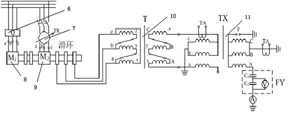
[0021] Example 2, such as figure 2 , the difference from embodiment 1 is that the test power supply module 1 can also be a frequency multiplier power supply composed of two motors, including a three-phase rotor wound asynchronous motor 9 and a three-phase asynchronous squirrel-cage motor 8, a three-phase asynchronous squirrel-cage motor The cage motor 8 is used to drive the three-phase rotor wound asynchronous motor 9, the three-phase asynchronous squirrel cage motor 8 is provided with a starter 6, the three-phase rotor wound asynchronous motor 9 is provided with a voltage regulator 7, and the three-phase rotor The wound asynchronous motor 9 is connected to a first step-up transformer 10 , and the first step-up transformer 10 is connected to a voltage division measurement system 11 . When in use, first start the squirrel cage motor M1 to the rated speed, and then use a three-phase power supply with the opposite phase sequence to the squirrel cage motor, and excite the stator ...
Embodiment 3
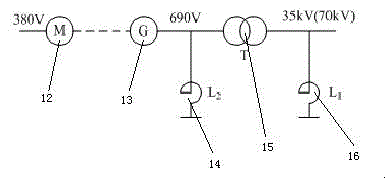
[0022] Example 3, such as image 3 , the difference from embodiment 1 is that the test power module 1 can also be an intermediate frequency brushless excitation synchronous motor unit composed of an asynchronous induction motor 12 and a brushless intermediate frequency synchronous motor 13, and the brushless intermediate frequency synchronous motor 13 and the second booster The transformer 15 is connected, the iron core reactor 14 is arranged between the brushless intermediate frequency synchronous motor 13 and the second step-up transformer 15 , and the air-core reactor body 16 is connected with the second step-up transformer 15 . Its working principle is: the intermediate frequency generator sends out single-phase or three-phase AC power with a certain frequency (250Hz), which is boosted by the intermediate transformer, and at the same time, the compensation reactor is used to adjust and compensate the capacitive current of the tested transformer to obtain the required the t...
PUM
 Abstract
Description
Claims
Application Information
 - R&D
- Intellectual Property
- Life Sciences
- Materials
- Tech Scout
- Unparalleled Data Quality
- Higher Quality Content
- 60% Fewer Hallucinations
Browse by: Latest US Patents, China's latest patents, Technical Efficacy Thesaurus, Application Domain, Technology Topic, Popular Technical Reports.
© 2025 PatSnap. All rights reserved.Legal|Privacy policy|Modern Slavery Act Transparency Statement|Sitemap|About US| Contact US: help@patsnap.com


