

Rotary optical probe
A technology of rotating detectors and optical paths, applied in instruments, sensors, measuring devices, etc., can solve the problems of end face damage and low reliability, and achieve high reliability, low cost, and the effect of suppressing light loss or reflection ghosting
- Summary
- Abstract
- Description
- Claims
- Application Information
AI Technical Summary
Problems solved by technology
Method used
Image

Examples
no. 1 approach
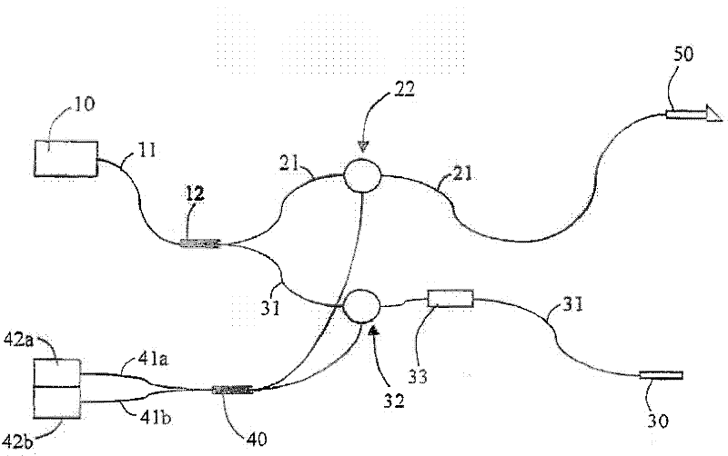
[0049] figure 1 It is a configuration diagram showing an example of an optical tomography apparatus to which the present invention is applicable. The optical tomography device is constituted as a Michelson interferometer using a low-coherence light source, which includes: a light source 10; a coupler 12; circulators 22, 32; an attenuator 33; a detector 50; a reference mirror 30; a coupler 40; Motion detectors 42a, 42b; and a plurality of optical paths 11, 21, 31, 41a, 41b, etc. The optical paths 11, 21, 31, 41a, 41b include flexible single-mode optical fibers.
[0050] The light source 10 is composed of an SLD or the like, and emits low-coherence light having a center wavelength of 1.3 μm and an oscillation spectral width of about 50 nm, for example. Light from light source 10 reaches coupler 12 through optical path 11 .
[0051] The coupler 12 is composed of a fiber coupler, a beam splitter, or the like, and functions as a light splitting unit that splits the light from t...
no. 2 approach
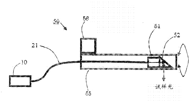
[0069] image 3 It is a block diagram showing the sensor of the second embodiment. The probe 50 includes an optical path 21 made of optical fibers, an objective lens 51 , a mirror member 52 , a rotation holding member 55 , a rotation vibration mechanism 56 , a sheath 57 , a sheath holding member 58 , and the like. Regarding the structure and operation of the rotational scanning of the sample light, due to the figure 2 The same is true for the first embodiment, so repeated description thereof will be omitted.
[0070] The sheath 57 is a hollow cylindrical member made of a hard material such as metal or plastic, or a bendable soft material, and rotatably supports the rotation holding member 55 inside. The sheath holding member 58 fixes the sheath 57 and restricts rotational movement of the sheath 57 .
[0071] In the present embodiment, a fixed holding member 25 for limiting the twist range is provided in the middle of the optical path 21 . The provision of the fixed holding...
no. 3 approach
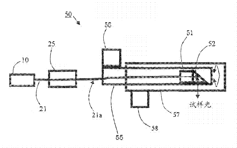
[0073] Figure 4 It is a block diagram showing the sensor of the third embodiment. The probe 50 includes an optical path 21 made of optical fibers, an objective lens 51 , a mirror member 52 , a rotation holding member 55 , a rotation vibration mechanism 56 , a sheath 57 , a sheath holding member 58 , and the like. Regarding the structure and operation of the rotational scanning of the sample light, due to the figure 2 The same is true for the first embodiment, so repeated description thereof will be omitted. In addition, regarding the structure of the sheath 57, due to the image 3 The same is true for the second embodiment, so repeated description thereof will be omitted.
[0074] Also in this embodiment, like the second embodiment, a fixing holding member 25 for limiting the twist range is provided in the middle of the optical path 21 . The area of the torsional portion 21 a that generates torsional vibration in the entire optical path 21 is limited by the installation...
PUM
| Property | Measurement | Unit |
|---|---|---|
| Wavelength | aaaaa | aaaaa |
Abstract
Description
Claims
Application Information