Active oxygen generator
一种生成装置、活性氧的技术,应用在氧气制备、氧气/臭氧/氧化物/氢氧化物、电极等方向,能够解决不能避免装置大型化、电量多等问题,达到构成简易化、增大活性氧量、构成小型化的效果
- Summary
- Abstract
- Description
- Claims
- Application Information
AI Technical Summary
Problems solved by technology
Method used
Image

Examples
Embodiment approach 1
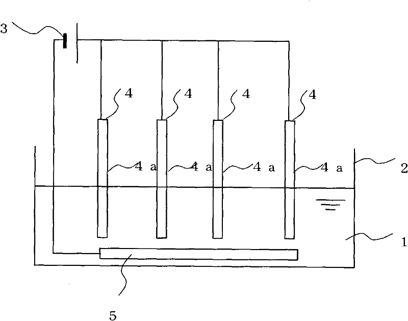
[0020] figure 1 It is a schematic cross-sectional view showing the configuration of the active oxygen generator according to Embodiment 1 of the present invention. This active oxygen generating device is provided with a cathode 4 made of a plate-shaped base material 4a containing a conductive polymer, a conductive anode 5, and a power supply 3 for passing electricity between the two electrodes 4 and 5 through water 1 in which oxygen is dissolved, And the water storage part 2 that stores water 1. Active oxygen is generated by passing electricity between the cathode 4 and the anode 5 from the power source 3 through the water 1 stored in the water storage unit 2 .
[0021] The cathode 4 is composed of a plurality of base materials 4a formed in a plate shape (disc shape, square plate shape, etc.), and one plate-shaped anode 5 straddles the plurality of base materials 4a and is connected to each of the plurality of base materials 4a. It is arranged at the bottom of the water stor...
Embodiment approach 2
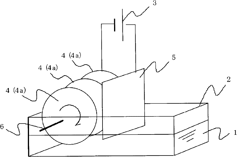
[0034] Next, Embodiment 2 of the present invention will be described. image 3 It is a schematic diagram showing the configuration of an active oxygen generator according to Embodiment 2 of the present invention. Here, above the water storage part 2, a conductive shaft 6 whose axial direction is in the horizontal direction is rotatably arranged, and a plurality of plate-shaped (preferably disc-shaped) substrates are arranged at intervals on the shaft 6. The material 4a forms the cathode 4 . The cathode 4 is installed so that a part of each base material 4a is immersed in the water 1 stored in the water storage part 2, and the surface of each base material 4a immersed in the water 1 rotates as the shaft 6 rotates. Therefore, as the cathode 4 rotates, the surface of each base material 4a contacts the water 1 and the air alternately.
[0035] On the other hand, the plate-shaped anode 5 is vertically arranged in the water storage part 2 with its planar part parallel to the axial d...
Embodiment approach 3
[0042] Next, use Figure 5 Embodiment 3 of the present invention will be described. Figure 5 It is a schematic configuration diagram of an active oxygen generation device according to Embodiment 3 of the present invention. This active oxygen generator has a water outlet 7 and a water outlet 8 for water 1 in a water storage unit 2 . In addition, above the water storage part 2, a conductive shaft 6 whose axial direction is horizontal is arranged in a rotatable manner, and a plurality of plate-shaped (preferably disc-shaped) base materials 4a are arranged at intervals on the shaft 6. , forming the cathode 4 . The cathode 4 with Figure 4 Similarly, a part of each base material 4 a is provided so as to be immersed in the water 1 stored in the water storage unit 2 , and the surface of each base material 4 a immersed in the water 1 rotates as the shaft 6 rotates. In addition, a part of the bottom surface or the side surface of the water storage part 2 perpendicular to each base...
PUM
 Abstract
Description
Claims
Application Information
 - R&D
- Intellectual Property
- Life Sciences
- Materials
- Tech Scout
- Unparalleled Data Quality
- Higher Quality Content
- 60% Fewer Hallucinations
Browse by: Latest US Patents, China's latest patents, Technical Efficacy Thesaurus, Application Domain, Technology Topic, Popular Technical Reports.
© 2025 PatSnap. All rights reserved.Legal|Privacy policy|Modern Slavery Act Transparency Statement|Sitemap|About US| Contact US: help@patsnap.com