Method and device for detecting polarization extinction ratio of optical polarizer

A polarization extinction ratio and polarization device technology, applied in the field of optical measurement, can solve problems such as unfavorable system operation, increased system cost, and direct impact of extinction ratio on equipment performance, etc., to achieve accurate measurement results, improve measurement accuracy, and easy to build.

Inactive Publication Date: 2011-09-14
TIANJIN UNIV +1
View PDF5 Cites 66 Cited by
  • Summary
  • Abstract
  • Description
  • Claims
  • Application Information

AI Technical Summary

Problems solved by technology

[0008] (5) In SDH equipment, the extinction ratio of the optical transmitter directly affects the performance of the equipment. Too large or too small extinction ratio is not conducive to the operation of the system
This method increases the cost of the system due to the use of dual optical paths

Method used


Image

  • Method and device for detecting polarization extinction ratio of optical polarizer
  • Method and device for detecting polarization extinction ratio of optical polarizer
  • Method and device for detecting polarization extinction ratio of optical polarizer

Examples


Embodiment 1

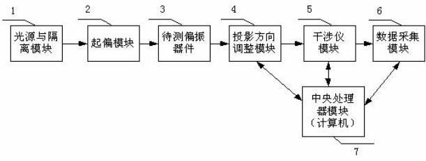
[0050] Such as Figure 7 Shown is the system structure diagram of the best realization device for the extinction ratio test of the polarizing device described in the present invention.

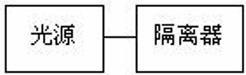
[0051] 1. The light source and isolator module is composed of SLD light source (center wavelength is 1310nm) and isolator;

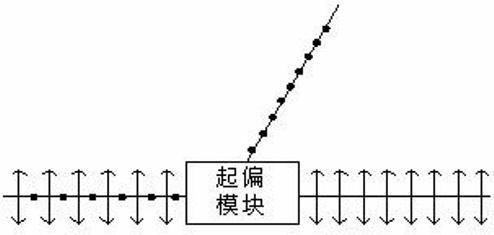
[0052] 2. The polarizing module is a fiber optic polarizer;

[0053] 3. The optical polarization device to be tested selects a 3-meter-long panda polarization-maintaining fiber;

[0054] 4. The projection direction adjustment module is composed of a rotatable half-wave plate and a Gran prism;

[0055] 5. The interferometer module selects Michelson interferometer;

[0056] 6. The data acquisition module adopts NI USB6251;

[0057] Seven, the central processing unit module is made up of computer and software program. The software is written in LABVIEW language, which can realize data processing, hardware control and calculation of polarization extinction ratio.

[00...


PUM


Abstract

The invention provides a method and device for detecting a polarization extinction ratio of an optical polarizer. The detection method comprises the following steps of: making linear polarized light incident along a principal axis of an optical polarizer to be detected, and obtaining two light signals on two orthogonal optical axes at an outgoing end due to polarization crosstalk; interfering and carrying out photoelectric conversion and data acquisition on interfering light signals to obtain one group of discrete voltage signal values reflecting the interfering light intensity signals; and calculating coupling intensity h at each coupling spot based on a formula (1), and calculating an extinction ratio of the optical polarizer to be detected based on a formula (2). The device sequentially comprises a light source, an isolator module, a polarization module, the optical polarizer to be detected, a projection direction regulating module, an interferometer module, a data acquisition module and a central processor module. The invention has the advantage that the coupling intensity of the coupling spots is detected to induce the polarization extinction ratio, so that the measurement result is accurate. The invention is suitable for various optical polarizers, such as polarization maintaining fibers, polarization maintaining fiber couplers, polarizers and the like and has certain universality.

Description

technical field [0001] The invention relates to a method for measuring parameters of an optical polarization device, and belongs to the technical field of optical measurement, in particular to a test device and a test method for the polarization extinction ratio of an optical polarization-maintaining device based on an interferometry method. Background technique [0002] Extinction ratio is an important index to measure the stability of polarization state of polarization-maintaining fiber (such as polarization-maintaining fiber, polarization-maintaining fiber coupler, polarizer, prism, crystal). When a beam of linearly polarized light is incident along a certain axis of the polarizing device, due to the residual stress inside the polarizing device, or the stress caused by thermal inhomogeneity, and the imperfection of the manufacturing process, the geometric shape of the optical polarizing device is not completely ideal, which will cause Originally isotropic substances appea...

Claims


Application Information

Patent Timeline
Patent Type & Authority Applications(China)
IPC IPC(8): G01M11/02
Inventor 张红霞温国强郑光金陈信伟贾大功叶雯婷刘铁根张以谟
Owner TIANJIN UNIV
Why Eureka
Try Eureka