Static discharge ESD protective circuit
An ESD protection, electrostatic discharge technology, applied in emergency protection circuit devices, emergency protection circuit devices for limiting overcurrent/overvoltage, circuit devices, etc., can solve problems such as circuit effects, reduce the possibility and enhance current The effect of conduction capability and improved discharge capability
- Summary
- Abstract
- Description
- Claims
- Application Information
AI Technical Summary
Problems solved by technology
Method used
Image
Examples
Embodiment 1
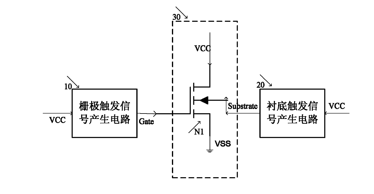
[0053] Please refer to figure 1 , an electrostatic discharge ESD protection circuit, comprising an electrostatic discharge branch 30 , a gate trigger signal generating circuit 10 and a substrate trigger signal generating circuit 20 .
[0054] Wherein, the electrostatic discharge branch 30 includes one or more MOS transistors, and the types of these MOS transistors may be NMOS transistors or PMOS transistors. When the electrostatic discharge branch 30 includes a plurality of MOS transistors, these MOS transistors form an electrostatic discharge branch in series, in parallel, or in series and parallel. The electrostatic discharge branch 30 includes two external input terminals, which are respectively used to connect to the power supply VCC and the ground VSS, or to connect to the external pad PAD and the ground VSS, and are used to pass the static electricity generated by the power supply VCC or the pad PAD through the static electricity. The discharge branch 30 transmits to th...
Embodiment 2
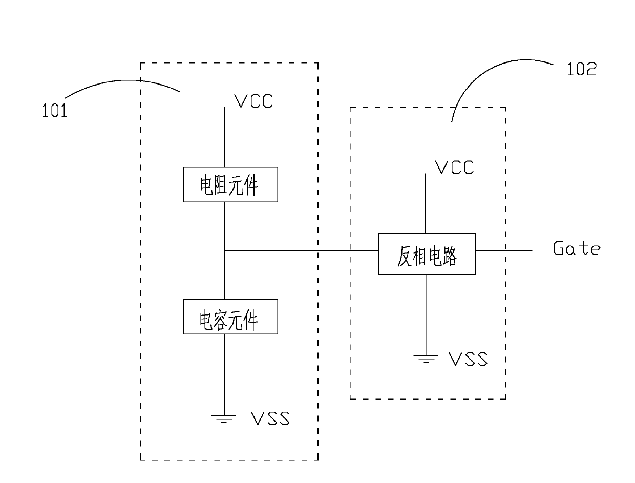
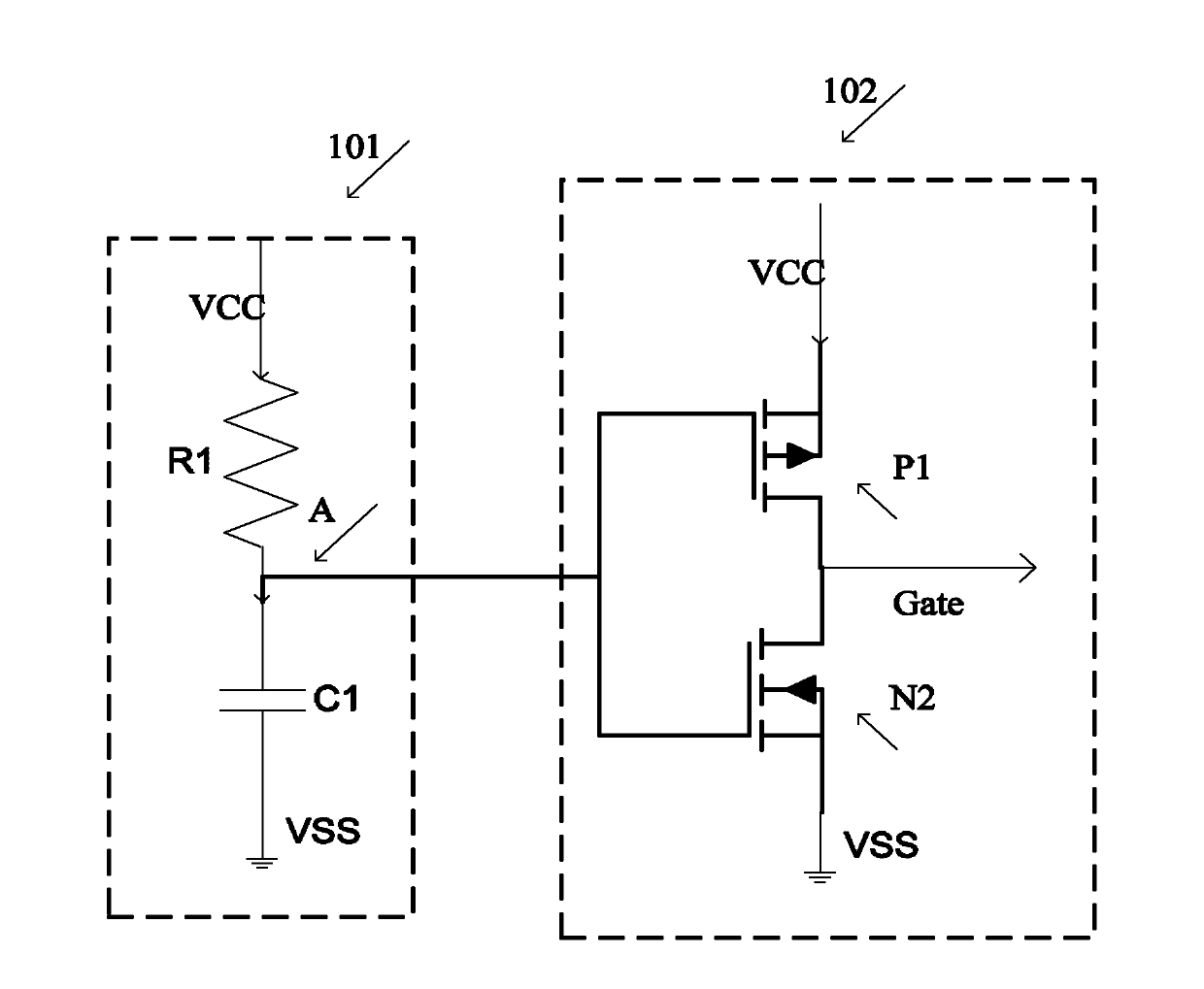
[0064] On the basis of embodiment 1, refer to Figures 2 to 5 The electrostatic discharge protection circuit when the electrostatic discharge branch circuit includes an NMOS transistor is described.
[0065] The electrostatic discharge branch circuit includes: an NMOS tube. The NMOS transistor includes a gate, a first electrode, a second electrode and a substrate. Wherein, the gate is connected to the output end of the gate trigger signal generating circuit, and the output end of the gate trigger signal generating circuit is used to output the gate trigger signal; the first electrode is a drain and is connected to a power supply; the second electrode is a source , connected to ground; the substrate is connected to the output terminal of the substrate trigger signal generating circuit, and the output terminal of the substrate trigger signal generating circuit is used to output the substrate trigger signal.
[0066] Such as figure 2 As shown, the gate trigger signal generati...
Embodiment 3
[0084] On the basis of embodiment 1 and embodiment 2, continue to refer to Image 6 The situation when the electrostatic discharge branch 30 includes a PMOS transistor will be described.
[0085] The electrostatic discharge branch circuit includes: a PMOS element. The PMOS element includes a gate, a first electrode, a second electrode and a substrate. Wherein, the gate is connected to the output end of the gate trigger signal generating circuit; the first electrode is the drain and is connected to the ground; the second electrode is connected as the source and is connected to the power supply; the substrate is connected to the substrate trigger signal generating circuit output.
[0086] In one implementation manner, the gate trigger signal generation circuit 10 includes: a first detection circuit.
[0087] The first detection circuit includes: a first resistance element and a first capacitance element. One end of the first resistive element is connected to the power supply...
PUM
 Abstract
Description
Claims
Application Information
 - R&D
- Intellectual Property
- Life Sciences
- Materials
- Tech Scout
- Unparalleled Data Quality
- Higher Quality Content
- 60% Fewer Hallucinations
Browse by: Latest US Patents, China's latest patents, Technical Efficacy Thesaurus, Application Domain, Technology Topic, Popular Technical Reports.
© 2025 PatSnap. All rights reserved.Legal|Privacy policy|Modern Slavery Act Transparency Statement|Sitemap|About US| Contact US: help@patsnap.com


