Supercharge Your Innovation With Domain-Expert AI Agents!

Synchronous circuit for switching power supply

A technology of synchronous circuit and switching power supply, applied in the direction of electrical components, output power conversion devices, etc., can solve the problems of frequency inconsistency, cost increase, efficiency reduction, etc., and achieve the effect of simple circuit structure, interference prevention, and reliable synchronous work

Inactive Publication Date: 2011-09-14
WEIHAI DONGXING ELECTRONICS
View PDF0 Cites 0 Cited by
  • Summary
  • Abstract
  • Description
  • Claims
  • Application Information

AI Technical Summary

Problems solved by technology

If linear voltage regulation is used, the problem of voltage accuracy can be solved, but at the same time it brings about a decrease in efficiency and an increase in heat generation, and the overcurrent and short circuit protection are not good; the use of two discrete power supply designs requires accurate and consistent frequencies , to limit the frequency within a small fixed range, and reduce noise; and the frequency control of most power supply control chips at present is to determine the operating frequency of the power supply through an external RC timing, and the precision of the resistor and capacitor is the same as that of the chip. The error will cause the frequency of the two power supplies to be inconsistent
At present, the most widely used is to use the triangular wave generated by 555 as the oscillation frequency, but it increases the complexity of the circuit, the cost will also increase, and the most important thing is that the efficiency will decrease.

Method used


Image

  • Synchronous circuit for switching power supply
  • Synchronous circuit for switching power supply

Examples


Embodiment Construction

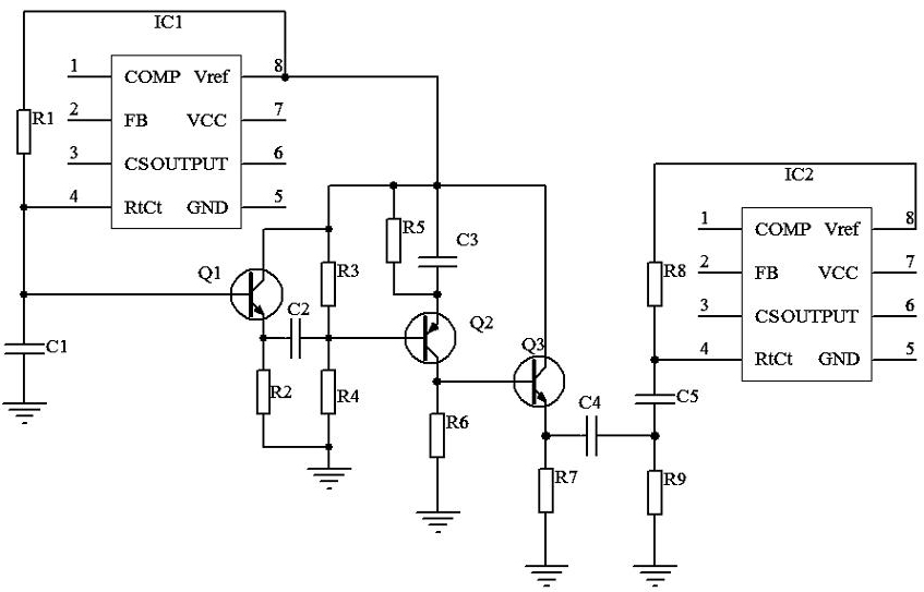
[0009] figure 1 Among them, the present invention is provided with main control chip IC1 and slave control chip IC2, and main control chip IC1 and slave control chip IC2 adopt UC3842 chip, and resistance R1 is connected between the reference pin 8 of main control chip IC1 and the oscillation pin 4, and capacitor C1 determines the frequency of the main control chip IC1; the base of the triode Q1 is connected to the oscillation pin 4 of the main control chip IC1, the emitter of the triode Q1 is connected to the capacitor C2 and the resistor R2, the collector of the triode Q1 is connected to the reference voltage pin 8 of the main control chip IC1, and the resistor R3, resistor R5, capacitor C3, and the collector of the transistor Q3 are connected; one end of the resistor R2 is connected to the emitter of the transistor Q1, and the other end of the resistor R2 is connected to GND; one end of the capacitor C2 is connected to the emitter of the transistor Q1, and the other end of th...


PUM


Abstract

The invention relates to a synchronous circuit for a switching power supply, belonging to the field of switch power supplies. An R1 is connected between a reference pin 8 and an oscillation pin 4 of a primary control chip and determines the frequency of the primary control chip with C1; the base of Q1 is connected with the oscillation pin of the primary control chip, an emitter is connected with C2 and R2, a collector is connected with the reference voltage pin of the primary control chip and the collectors of R3, R5, C3 and Q3; one end of R2 is connected with the emitter of Q1 and the other end of R2 is connected with GND; one end of C2 is connected with the emitter of Q1 and the other end of C2 is connected with the bases of R3, R4 and Q2; one end of R3 is connected with the collector of Q1and the other end of R3 is connected with the base end of Q2, C2 and R4; the other end of R4 is connected with GND; one end of R6 is connected with the collector of Q2, the base of Q3 and the other end of R6 is connected with GND; the collector of Q3 is connected with the reference voltage pin of the primary control chip and the of emitter Q3 is connected with R7 and C4, the other end of R7 is connected with GND and the other end of C4 is connected with C5 and R9; the other end of R9 is connected with GND; the other end of C5 is connected with R8 and the oscillation pin of a subsidiary control chip and the other end of R8 is connected with the reference voltage pin of the subsidiary control chip.

Description

technical field [0001] The invention relates to the field of switching power supplies, in particular to a switching power supply synchronous circuit. Background technique [0002] As we all know, in many cases, a switching power supply requires multiple outputs. In order to ensure the accuracy of the output or design difficulties, it is often necessary to divide a power supply into two independent power supplies for design; especially in communication power supplies, the voltage accuracy is required to be compared. High, the power is relatively large, and the power spectrum is required to be single, so as to avoid the non-linear device mixing various frequencies due to inconsistency in frequency. When this mixing signal enters the same frequency band of the band-pass filter of the communication system, it will Interference with communication signals. If linear voltage regulation is used, the problem of voltage accuracy can be solved, but at the same time it brings about a d...

Claims


Application Information

Patent Timeline
Patent Type & Authority Applications(China)
IPC IPC(8): H02M1/44
Inventor 姜永巍
Owner WEIHAI DONGXING ELECTRONICS
Features
  • R&D
  • Intellectual Property
  • Life Sciences
  • Materials
  • Tech Scout
  • Unparalleled Data Quality
  • Higher Quality Content
  • 60% Fewer Hallucinations
Learn More