Compound pulverizing system based on coal pulverizer

A technology of a pulverizing system and a coal mill, which is used in solid separation, separation of solids from solids by air flow, grain processing, etc. Increase ventilation and other issues to achieve the effect of improving stability and combustion efficiency, improving reliability and flexibility, and stabilizing ignition and combustion

Inactive Publication Date: 2013-03-06
ZHUZHOU HUAYIN THERMAL POWER GENERATION +1
View PDF9 Cites 0 Cited by
  • Summary
  • Abstract
  • Description
  • Claims
  • Application Information

AI Technical Summary

Problems solved by technology

[0002] The following contradictions have always existed in the design and operation of the direct blowing pulverization system based on various steel ball coal mills (single-inlet-single-outlet and double-inlet-double-outlet type): If the output of the steel ball coal mill is too large, then The power consumption of the pulverizing unit will always be high during operation, and the economy will be worse under low load conditions; if the output of the ball mill is too small, the calorific value, moisture, ash, Due to factors such as changes in the property coefficient and the particle size of the raw coal, the pulverized coal becomes coarser during operation, the pulverizing output is insufficient, the combustion stability and combustion efficiency of the boiler decrease, and the boiler output is insufficient.
The reasons for this situation are: (1) When the quality of coal combustion decreases, the absolute amount of pulverized coal will increase. If the output margin of the coal mill is not enough, it will lead to insufficient pulverized output of the coal mill, which cannot meet the high load of the boiler or Requirements for full output operation; (2) When the coal quality is poor and the boiler is required to operate at high load or full load, the ventilation in the coal mill will increase, which will cause the pulverized coal at the outlet of the coal mill to become coarser, thus The combustion stability and combustion efficiency in the furnace will decrease, the carbon content of boiler fly ash will increase, and the boiler efficiency will decrease; (3) In the direct blowing pulverization system, the pulverization amount of the steel ball mill must change with the boiler load However, when the load of the boiler decreases, the pulverized amount of the coal mill decreases, and for the steel ball mill, the difference between the no-load power consumption and the full-load power consumption is very small, so the unit power consumption of the steel ball mill direct blowing pulverization system increases with the The drop in load increases proportionally to the

Method used


Image

  • Compound pulverizing system based on coal pulverizer
  • Compound pulverizing system based on coal pulverizer
  • Compound pulverizing system based on coal pulverizer

Examples


Embodiment 1

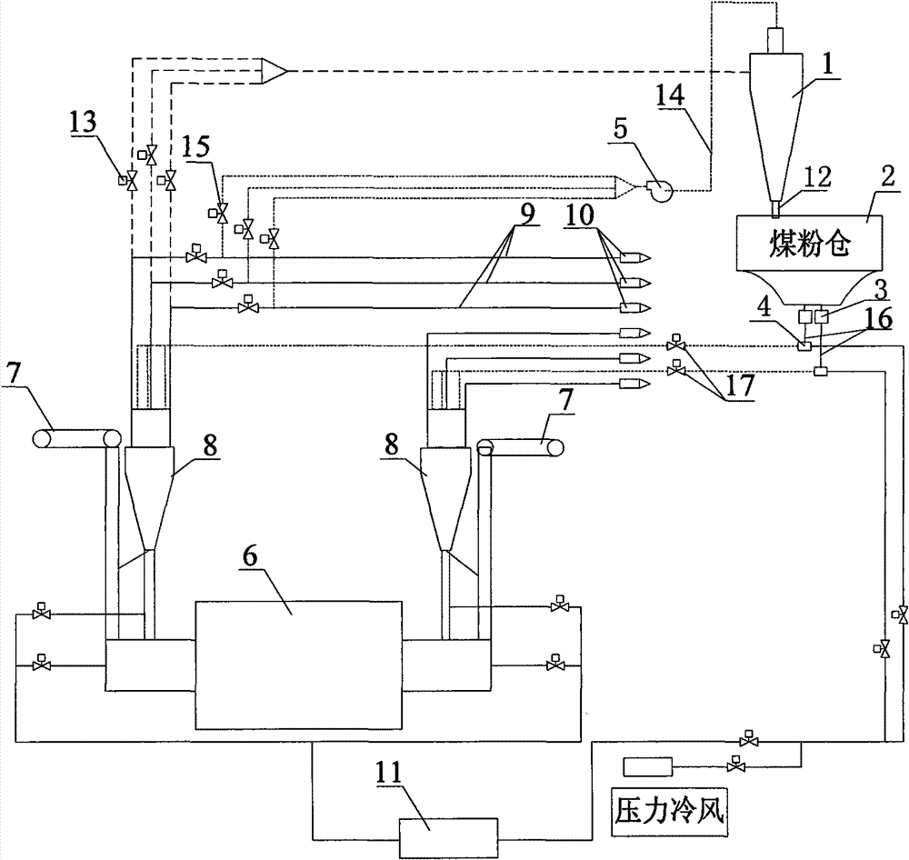
[0023] Embodiment 1: as figure 1 As shown, the compound pulverization system based on the coal mill of the present invention includes a fine powder separator 1, a pulverized coal bin 2, a pulverizer feeder 3, a pulverized coal mixer 4, a pulverizer discharger 5, a coal pulverizer 6, a pulverized coal feeder Coal machine 7, coarse powder separator 8 and primary air supply mechanism 11, coal mill 6 adopts double-inlet and double-outlet steel ball coal mill, and two ends of coal mill 6 are respectively connected with a coarse powder separator 8 and a Coal feeder7. The coal feeder 7 is connected to the inlet end of the coal mill 6, and the outlet end of the coal mill 6 is connected to the inlet end of the coarse powder separator 8. The powder pipe 12 and the switching valve 13 of the powder feeding pipe of the powder bin are connected with the fine powder separator 1, and the separated fine coal powder enters into the coal powder bin 2 after passing through the fine powder separa...

Embodiment 2

[0031] Embodiment 2: as Figure 6 As shown, the compound pulverization system based on the coal mill of the present invention includes a fine powder separator 1, a pulverized coal bin 2, a pulverizer feeder 3, a pulverized coal mixer 4, a pulverizer discharger 5, a coal pulverizer 6, a pulverized coal feeder Coal machine 7, coarse powder separator 8 and primary air supply mechanism 11, coal mill 6 adopts double-inlet and double-outlet steel ball coal mill, and two ends of coal mill 6 are respectively connected with a coarse powder separator 8 and a Coal feeder7. The coal feeder 7 is connected to the inlet end of the coal mill 6, and the outlet end of the coal mill 6 is connected to the inlet end of the coarse powder separator 8. The powder pipe 12 and the switching valve 13 of the powder feeding pipe of the powder bin are connected with the fine powder separator 1, and the separated fine coal powder enters into the coal powder bin 2 after passing through the fine powder separ...


PUM


Abstract

A compound pulverizing system based on a coal pulverizer comprises a fine powder separator, a coal dust warehouse, a coal dust feeder, a coal dust mixer, a mill fan, a coal pulverizer, a coal feeder, a crude powder separator and a primary air supply mechanism, wherein the coal feeder is connected with an inlet port of the coal pulverizer; an outlet port of the coal pulverizer is connected with the inlet port of the crude powder separator; an outlet port of the crude powder separator is divided into two routes with one route leading to the fine powder separator through a powder pipe of the coal dust warehouse and transfer valves and the other route leading to primary air pipelines through transfer valves; an exhaust gas outlet port of the fine powder separator is connected with the primary air pipelines through an exhaust pipe, the mill fan and transfer valves; a powder outlet port of the fine powder separator is connected with an inlet port of the coal dust warehouse; and an outlet port of the coal dust warehouse is connected with the primary air pipelines through powder supply pipes, the coal dust feeder and the coal dust mixer. The compound pulverizing system based on a coal pulverizer in the invention has advantages of simple and compact structure, low cost, low energy consumption and good pulverizing effect, and can be widely applied.

Description

technical field [0001] The invention mainly relates to the field of coal powder preparation system in coal-fired thermal power plants, in particular to a composite pulverizing equipment. Background technique [0002] The following contradictions have always existed in the design and operation of the direct blowing pulverization system based on various steel ball coal mills (single-inlet-single-outlet and double-inlet-double-outlet type): If the output of the steel ball coal mill is too large, then The power consumption of the pulverizing unit will always be high during operation, and the economy will be worse under low load conditions; if the output of the ball mill is too small, the calorific value, moisture, ash, Due to factors such as changes in the property coefficient and the particle size of raw coal, the pulverized coal becomes coarser during operation, the pulverizing output is insufficient, the combustion stability and efficiency of the boiler decrease, and the boil...

Claims


Application Information

Patent Timeline
Patent Type & Authority Patents(China)
IPC IPC(8): B02C17/00B02C23/20B02C23/02B02C23/00B07B7/04B07B11/02
Inventor 陈泽彦陈冬林刘应山鄢晓忠
Owner ZHUZHOU HUAYIN THERMAL POWER GENERATION
Why Eureka
Try Eureka