Numerical control double-station mould engraving and milling machine

An engraving and milling machine, dual-station technology, applied in the direction of manufacturing tools, metal processing mechanical parts, milling machines, etc., can solve problems such as productivity limitations, uneven operating proficiency, and difficult to guarantee requirements.

Inactive Publication Date: 2011-09-21
DOUBLE HEAD CNC
View PDF2 Cites 25 Cited by
  • Summary
  • Abstract
  • Description
  • Claims
  • Application Information

AI Technical Summary

Problems solved by technology

[0002] Shoe molds, blade molds, bottle molds and other molds, and general metal parts generally have the same technical specifications in size, tolerance, surface roughness and other requirements during the production process. In the process of mass production, if traditional processing The method needs to be processed and produced one by one on a machine tool. The parts processed and produced per unit time are limited by the number of machine tools and the number of operators. In addition, the operating proficiency of the operators varies, and the requirements in the production cycle are relatively limited. The productivity within a certain period of time is bound to be greatly restricted
And in the processing and production process of some parts or molds, it is difficult to guarantee the required pairing by traditional processing methods.

Method used


Image

  • Numerical control double-station mould engraving and milling machine
  • Numerical control double-station mould engraving and milling machine
  • Numerical control double-station mould engraving and milling machine

Examples


Embodiment Construction

[0014] The present invention will be further explained below in conjunction with the drawings in the specification:

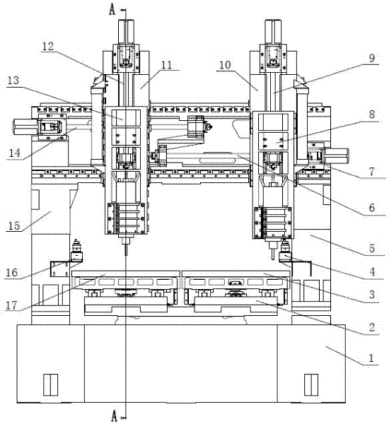
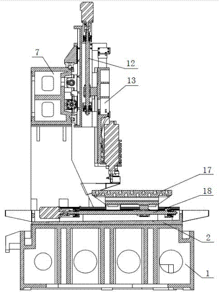
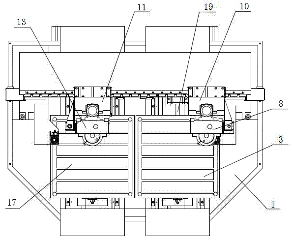
[0015] The CNC double-station mold engraving and milling machine includes a machine frame body 1. The machine frame body 1 is matched with a base 2, a left column 15 and a right column 5, and a cross beam 7 is arranged above the left column 15 and the right column 5. 7 The left X-axis linear slider guideway pair and the right X-axis linear slider guideway pair are respectively connected with the left X-axis sliding table 11 and the right X-axis sliding table 10, and respectively through the left X-axis ball screw pair 14, right The X-axis ball screw pair 6 is matched in transmission. The left X-axis sliding table 11 and the right X-axis sliding table 10 can perform related left and right movements on the beam 7 or one side is stationary and the other moves independently; the base 2 The left Y-axis linear slider guideway pair and the right Y-axis linear slider guid...


PUM


Abstract

The invention relates to a machine tool, in particular to a numerical control double-station mould engraving and milling machine. A foundation, a left vertical shaft and a right vertical shaft are arranged on a frame body of the machine in a matched way; a beam is arranged above the left vertical shaft and the right vertical shaft in a matched way; the beam is connected with a left X-axle sliding table and a right X-axle sliding table through a left X-axle linear sliding block guide rail pair and a right X-axle linear sliding block guide rail pair in a matched way and the beam is in transmission fit with the left X-axle sliding table and the right X-axle sliding table through a left X-axle ball screw pair and a right X-axle ball screw pair; the foundation is connected with a left Y-axle sliding table and a right Y-axle sliding table through a left Y-axle linear sliding block guide rail pair and a right Y-axle linear sliding block guide rail pair in a matched way and the foundation is in transmission fit with the left Y-axle sliding table and the right Y-axle sliding table through a left Y-axle ball screw pair and a right Y-axle ball screw pair; and the left X-axle sliding table and the right X-axle sliding table are connected with a left Z-axle sliding table and a right Z-axle sliding table through a left Z-axle linear sliding block guide rail pair and a right Z-axle linear sliding block guide rail pair in a matched way and the left X-axle sliding table and the right X-axle sliding table are in transmission fit with the left Z-axle sliding table and the right Z-axle sliding table through a left Z-axle ball screw pair and a right Z-axle ball screw pair. The efficiency of the numerical control double-station mould engraving and milling machine is two times that of the conventional machine tool.

Description

Technical field [0001] The invention relates to a machine tool, in particular to a numerical control double-station mold engraving and milling machine. Background technique [0002] Shoe molds, blade molds, bottle molds and other molds, as well as general metal parts, generally have the same requirements for dimensions, tolerances, surface roughness and other technical indicators during the production process. In the mass production process, such as using traditional processing The method requires one-by-one processing and production on a machine tool. The parts processed per unit time are limited by the number of machine tools and the number of operators. In addition, the operating proficiency of operators varies from good to bad, and the requirements in the production cycle are relatively limited. The productivity within the time limit is bound to be greatly restricted. In addition, some parts or molds are required to be matched in pairs during the processing and production pr...

Claims


Application Information

Patent Timeline
Patent Type & Authority Applications(China)
IPC IPC(8): B23C1/08B23Q5/027B23Q1/56
Inventor 郭云飞
Owner DOUBLE HEAD CNC
Why Eureka
Try Eureka