Hydraulic test system

A testing system and hydraulic technology, which is applied in hydraulic/pneumatic metering, measuring devices, and application of repetitive force/pulsation force to test material strength, etc. It can solve the problem that the clamp cannot clamp the target balloon, has large errors, and poor sealing performance And other issues

Active Publication Date: 2011-09-21
SHANGHAI NEURAZING CO LTD
View PDF5 Cites 12 Cited by
  • Summary
  • Abstract
  • Description
  • Claims
  • Application Information

AI Technical Summary

Problems solved by technology

[0004] At present, the existing automatic product for realizing pressure resistance test, fatigue test and compliance test is PT1000 produced by American INTERFACE company. In practical application, the fixture of the product cannot clamp the target balloon, and leakage will definitely occur during the test.
[0005] The control core adopts 51 series single-chip microcomputer. Since there is no external expansion memory, the storage capacity is limited. At present, only 20 test programs can be stored.
Moreover, when setting program parameters, they are all carried out in the lower computer, which is not efficient
The upper computer software is only responsible for receiving data, and cannot send commands to make the lower computer act
During pressure calibration, the chassis must be disassembled and the potentiometer knob adjusted, which is inconvenient, and only two points (zero pressure and full scale) are taken during pressure calibration. Since the pressure sensor also has linearity errors, two-point calibration is used. increase the error of the whole system
[0006] From the above description, it can be concluded that the existing automatic control detection system has a complex structure and poor sealing performance; it is controlled by a single-chip microcomputer, and the storage capacity is limited; the parameters of the test program are all stored in the lower computer, and currently only 20 test programs can be saved; The calibration process is too simple and the error is large

Method used


Image

  • Hydraulic test system
  • Hydraulic test system
  • Hydraulic test system

Examples


Embodiment Construction

[0101]The following will clearly and completely describe the technical solutions in the embodiments of the present invention with reference to the accompanying drawings in the embodiments of the present invention. Obviously, the described embodiments are only some, not all, embodiments of the present invention. Based on the embodiments of the present invention, all other embodiments obtained by persons of ordinary skill in the art without creative efforts fall within the protection scope of the present invention.

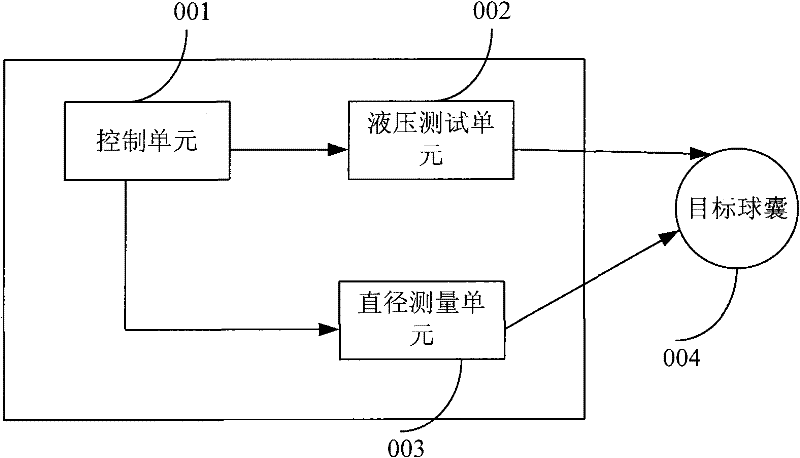
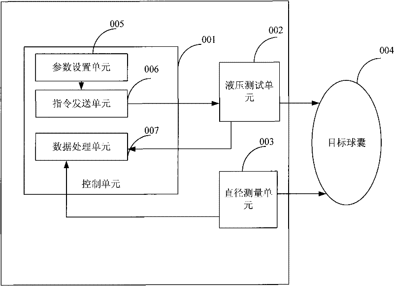
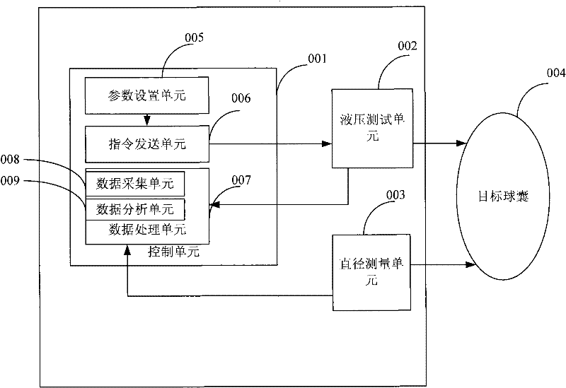
[0102] The system diagram of the hydraulic test system disclosed in the embodiment of the present invention is as follows figure 1 As shown, it includes: control unit 001, hydraulic test unit 002 and diameter measurement unit 003;

[0103] The control unit 001, the hydraulic test unit 002 and the diameter measurement unit 003 cooperate with each other to automatically realize the pressure resistance test, fatigue test, compliance test and / or pressure self-calibratio...


PUM


Abstract

The embodiment of the invention discloses a hydraulic test system which comprises a control unit, a hydraulic test unit and a diameter measurement unit, wherein the control unit, hydraulic test unit and diameter measurement unit are cooperated with one another to automatically realize a pressure resistance test, fatigability test, compliance test and / or pressure self calibration of a target ball sac; the control unit is used for setting the parameters of each test process; the hydraulic test unit is used for specifically implementing each test process; and the diameter measurement unit is used for measuring the diameter of the target ball sac. The hydraulic test system disclosed by the embodiment of the invention can automatically implement the fatigability test, pressure resistance test, compliance test and / or pressure self calibration of the target ball sac. The number of test programs stored by the control unit is not limited, and the setting of program parameters also can be performed in the control unit, thus being relatively visual and efficient. The software of the control unit can control the operation of the hydraulic test unit, and the hydraulic test unit does not need to be repeatedly operated during each operation.

Description

technical field [0001] The present invention relates to a medical testing system, and more particularly, to a hydraulic testing system. Background technique [0002] At present, in the interventional treatment of coronary heart disease, whether it is percutaneous transluminal coronary angioplasty or coronary artery stenting, a target balloon catheter is required to complete it. As the name suggests, the target balloon catheter has a target balloon at the end of the catheter, and the finished catheter generally has a target balloon in a folded state. According to the provisions of ISO25539-2, the target balloon catheter must meet the pressure resistance performance, fatigue performance and compliance performance. If pressure resistance is achieved manually, testing for fatigue requires an inflator with a pressure gauge and a stopwatch, and compliance requires a dial gauge. Manual testing is not easy to control, the efficiency is not high, and the differences between personn...

Claims


Application Information

Patent Timeline
Patent Type & Authority Applications(China)
IPC IPC(8): G01L1/02G01N3/36G01B13/08
Inventor 施重频孙健李勇孙冰王盛强徐益民
Owner SHANGHAI NEURAZING CO LTD
Why Eureka
Try Eureka