PLC (Programmable Logic Controller) type optical splitter testing method

A test method and optical splitter technology, which is applied in the direction of testing optical performance, etc., can solve the problems of low test efficiency and long test time, and achieve the effects of reducing artificial test errors, saving labor costs, and simple operation steps

Active Publication Date: 2011-09-21
上海乐通通信设备(集团)股份有限公司 +3
View PDF3 Cites 13 Cited by
  • Summary
  • Abstract
  • Description
  • Claims
  • Application Information

AI Technical Summary

Problems solved by technology

The disadvantage of this test method is that the test time is long and the test efficiency is extremely low.

Method used


Image

  • PLC (Programmable Logic Controller) type optical splitter testing method
  • PLC (Programmable Logic Controller) type optical splitter testing method
  • PLC (Programmable Logic Controller) type optical splitter testing method

Examples


Embodiment Construction

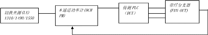
[0013] see image 3 , the embodiment of the present invention is an 8-channel optical power meter (8CH PM), which integrates 3 light sources of traditional test equipment, for example, the wavelength is 1310, 1550, 1490 nanometers (nm), and 1 3-way switching light source A switch, a polarization controller and 8 single-channel optical power meters are connected to a computer (not shown in the figure), and the test data can be selected according to actual needs after the test.

[0014] The method provided by the present invention is as follows: the above-mentioned 3-way switching optical switch is integrated into the above-mentioned 3-wavelength light source and connected through the above-mentioned 8-channel power meter, and the polarization controller is integrated into the 8-channel power meter, which is uniformly controlled by a computer. The light source is output by a light source line, and the output light source line is respectively calibrated by the 8 detection ports o...


PUM


Abstract

The invention relates to a PLC (Programmable Logic Controller) type optical splitter testing method, wherein a light source is output by a light source line; the output light source line enters the eight detection ports of an eight-channel power meter to be respectively calibrated and the initial value pO is tested; the rear light source line is connected with the single fiber of a PLC to be measured; the ribbon fiber of the PLC is connected with a ribbon fiber splitter through a ribbon fiber welding machine; the matched eight connectors are selected for the PLC finished product testing; each connector is respectively connected with the eight-channel power meter; a PDL (Polarization Dependent Loss) mode is selected; the switching of an optical switch in a three-wavelength light source and the action of a polarization controller in the eight-channel power meter are automatically controlled by a computer; and the simultaneous testing of the insertion loss of the three wavelengths corresponding to eight channels and the relevant loss of polarization can be finished once. The PLC type optical splitter testing method provided by the invention has the advantages of simple operation steps and high testing efficiency, ensures that the labor cost of testing personnel is saved and is simultaneously beneficial to the production management of the products, thereby improving the production efficiency and competitiveness of enterprises.

Description

Technical field: [0001] The invention relates to a testing method for a PLC type optical splitter Background technique [0002] With the gradual development of fiber-to-the-home (FTTH), the market demand for splitters with broadband splitters is growing rapidly. Compared with the traditional tapered splitter, the planar waveguide (PLC) device material and packaging technology have been continuously improved, making the PLC splitter more and more reflective not only in terms of technical indicators, but also in terms of production cost and scale. Take advantage of it. [0003] exist figure 1 In a typical E / GPON access solution, the ODN is an optical splitter 1:N, that is, a PLC type optical splitter. [0004] For the test method of traditional PLC optical splitter, see figure 2 , which is a single-channel single-index single-wavelength sequential measurement method. The test procedure is to first zero the light sources of 3 wavelengths (for example, 1310nm, 1550nm, and ...

Claims


Application Information

Patent Timeline
Patent Type & Authority Applications(China)
IPC IPC(8): G01M11/02
Inventor 李德红骆升王承波侯戟乐志强
Owner 上海乐通通信设备(集团)股份有限公司
Why Eureka
Try Eureka