Discharge lamp

A discharge lamp and discharge vessel technology, applied in the manufacture of discharge lamps, gas discharge lamps, and discharge tubes/lamps, etc., can solve the problems of blocking the emitter, destroying the strength of the electrode, and easily deforming the electrode, and achieves stable diffusion and stability. The effect of electrode strength

Active Publication Date: 2011-09-21
ORC MFG
View PDF5 Cites 0 Cited by
  • Summary
  • Abstract
  • Description
  • Claims
  • Application Information

AI Technical Summary

Problems solved by technology

[0006] Therefore, there is a problem that the emitter supply is interrupted at the low-density portion during lighting, and the emitter cannot be supplied lubricated to the front end of the cathode.
[0007] On the other hand, since the density distribution is not uniform as a whole, the strength of the electrode in the tip portion of the electrode is insufficient and the electrode is easily deformed
Furthermore, during lighting, the tip portion of the electrode becomes high temperature, and as a result, the high-density portion is easily thermally deformed, and there is a problem that the balance of electrode strength is broken.

Method used


Image

  • Discharge lamp
  • Discharge lamp
  • Discharge lamp

Examples


Embodiment Construction

[0042] Hereinafter, embodiments of the present invention will be described with reference to the drawings.

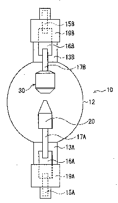
[0043]figure 1 It is a schematic cross-sectional view of the short-arc discharge lamp of the first embodiment.

[0044] The short-arc discharge lamp 10 has a transparent quartz glass arc tube 12, and inside the arc tube 12, a cathode 20 and an anode 30 are arranged to face each other with a predetermined interval therebetween. On both sides of the arc tube 12 , sealing tubes 13A and 13B made of quartz glass are provided continuously with the arc tube 12 and integrally formed. In the arc tube 12, rare gases such as tribute and argon are sealed.

[0045] Conductive electrode support rods 17A, 17B that support the cathode 20 and the anode 30 are arranged inside the sealed tubes 13A, 13B. Electrode support bars 17A, 17B are connected to conductive lead bars 15A, 15B via metal foils 16A, 16B, respectively. Sealing tubes 13A, 13B are welded to metal foils 16A, 16B, respect...


PUM

PropertyMeasurementUnit
diameteraaaaaaaaaa

Abstract

The present invention provides a discharge lamp which provides stable diffusion of a radiator and a stable electrode strength. The discharge lamp is provided with a cathode (20) which is provided with a sintered layer (sintered member) (24) on the front end (23) of the electrode, wherein the sintered layer is composed of a plurality of density inclination layers (26). Each density inclination layer is formed through periodically compressing the mixed powder of radiator powders such as barium oxide and high-melting-point powders such as tungsten into a dent part (25) of the cathode (20), and integrally performing SPS sintering. In each layer, the sintered member is inclined, and the density gradually reduces from the front side to the back side of the electrode.

Description

technical field [0001] The present invention relates to a discharge lamp in which an electrode is arranged in a luminous tube, and particularly relates to the structure of the tip portion of the electrode and its manufacturing method. Background technique [0002] In order to improve lamp startability, a sintered body containing emitters (electron-emitting substances) such as thorium oxide and barium oxide is buried at the tip of the cathode of the discharge lamp. As its production method, there is known a method in which, instead of first sintering a mixed powder of emitter powder and tungsten powder, it is press-inserted into a recess formed at the tip of the electrode, and then sintered ( Refer to Patent Document 1). [0003] The method of press-fitting the above-mentioned powder into the tip and then integrally sintering the electrode is aimed at suppressing evaporation of the emitter and facilitating the manufacture of the cathode. When the integral sintering process ...

Claims


Application Information

Patent Timeline
Patent Type & Authority Applications(China)
IPC IPC(8): H01J61/04H01J9/02
CPCH01J9/02H01J61/0732H01J61/0737
Inventor 上条享早川壮则片冈智史松木健芹泽和泉金井信夫
Owner ORC MFG
Why Eureka
Try Eureka