Pump for supplying high-pressure fuel

A high-pressure fuel and supply pump technology, which is applied to fuel injection pumps, fuel injection devices, liquid fuel engines, etc., can solve the problems of gnawing or wear of sliding parts, which cannot be guaranteed, and achieve the effect of reducing gnawing or wear.

Active Publication Date: 2011-09-21
HITACHI ASTEMO LTD
View PDF5 Cites 16 Cited by
  • Summary
  • Abstract
  • Description
  • Claims
  • Application Information

AI Technical Summary

Problems solved by technology

[0005] However, the central axis of the cylinder (guide area: 32) to be fitted into the pump housing (28) and the center of the plunger (piston: 40) inserted into the cylinder (guide area: 32) cannot be guaranteed. The axis is assembled coaxi

Method used


Image

  • Pump for supplying high-pressure fuel
  • Pump for supplying high-pressure fuel
  • Pump for supplying high-pressure fuel

Examples


Embodiment 1

[0049] pass Figure 1 to Figure 12 Examples of the present invention will be described.

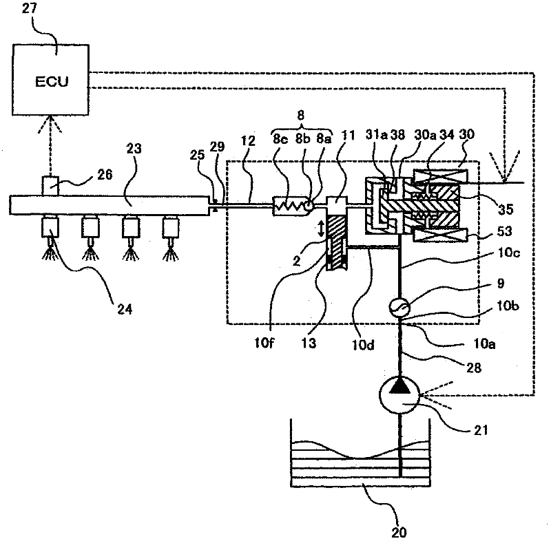
[0050] exist figure 1 In , the part enclosed by the dotted line represents the pump casing 1 of the high-pressure pump, and the mechanism and components shown in the dotted line represent the case of being integrated into the pump casing 1 of the high-pressure pump.

[0051] The fuel in the fuel tank 20 is pumped by the feed pump 21 based on a signal from the engine control unit 27 (hereinafter referred to as ECU), pressurized to an appropriate feed pressure, and delivered to the suction port 10a of the high-pressure fuel supply pump through the suction pipe 28 .

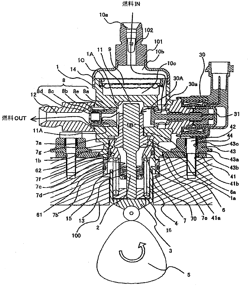
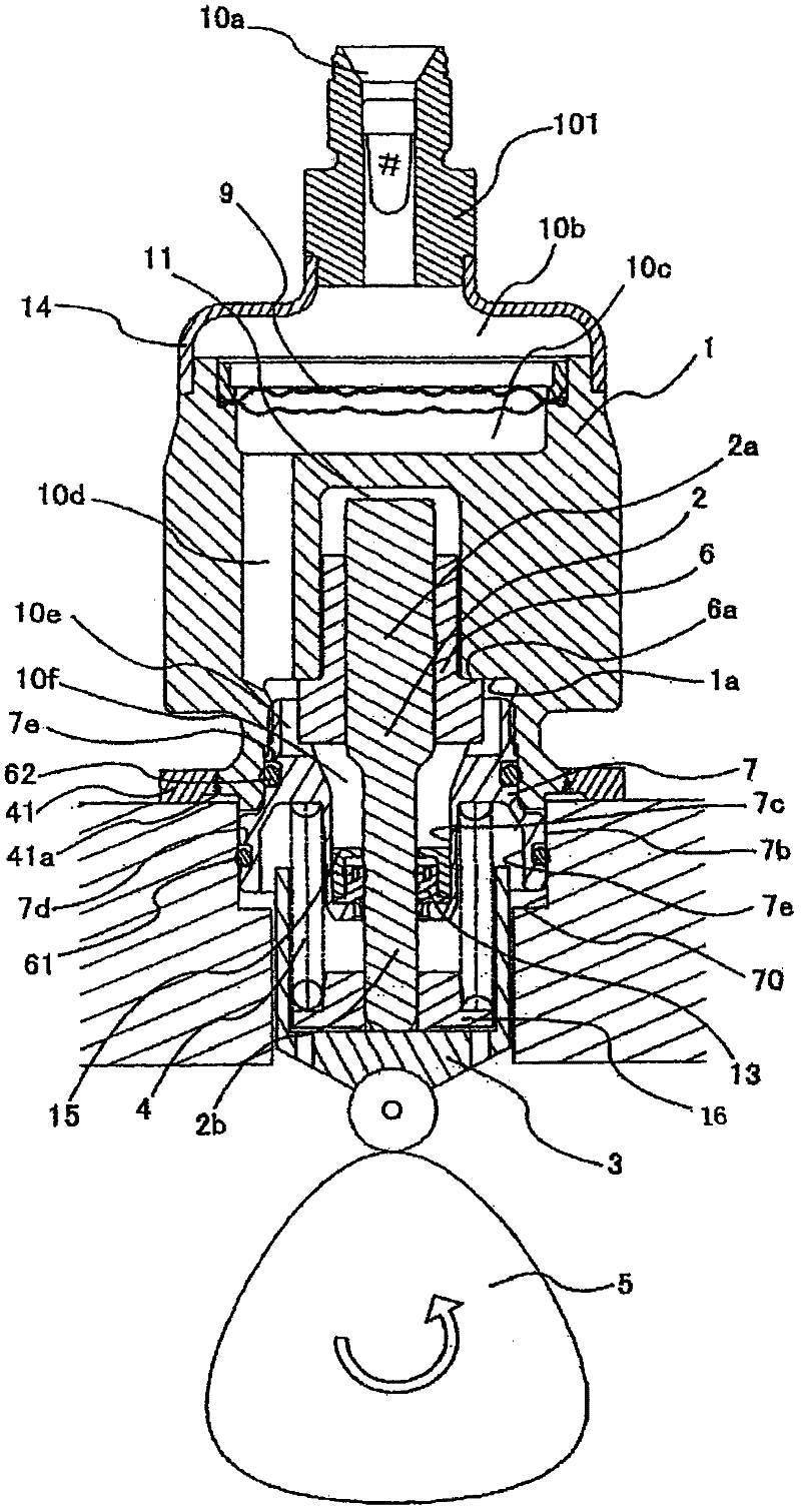
[0052] After passing through the suction port 10a, the fuel passes through the filter 102 fixed in the suction joint 101, then passes through the suction flow path 10b, the metal diaphragm dampers 9, 10c, and reaches the suction of the electromagnetically driven valve mechanism 30 constituting the capacity variable mechanism....

Embodiment approach 1

[0179] An electromagnetically driven valve mechanism having:

[0180] An outwardly opening valve member provided at the inlet of the fluid;

[0181] movable plunger operated by electromagnetic force;

[0182] fixing the working cylinder to the bracket of the pump housing;

[0183]A restricting member restricting the displacement of the plunger at a specific position;

[0184] a spring member biasing the movable plunger to a side opposite to the restricting member;

[0185] an electromagnetic drive mechanism that applies electromagnetic force to the movable plunger to apply force to the valve member and the movable plunger in a direction to close the fluid inlet;

[0186] The valve seat on which the valve member is tightly contacted and disengaged;

[0187] supporting the movable plunger as a reciprocating bearing member,

[0188] The valve seat and the bearing member are constituted as one part machined from the same member.

Embodiment approach 2

[0190] The electromagnetically driven valve mechanism according to Embodiment 1, wherein

[0191] fixing an anchor at the end of the movable plunger opposite the valve member,

[0192] the anchor is disposed facing said limiting member across a magnetic gap,

[0193] the restricting member constitutes a magnetic core portion of the electromagnetic drive mechanism,

[0194] A cover member made of a magnetic material that surrounds the anchor and the magnetic gap and seals the inside is fixed to the magnetic core portion of the restricting member,

[0195] An electromagnetic coil is mounted on the outer periphery of the cover member made of magnetic material,

[0196] A magnetic collar member is provided on its outer periphery, and the magnetic collar member cooperates with the anchor, the magnetic gap, the magnetic core portion, and the magnetic material cover member to form a magnetic path.


PUM


Abstract

A pump for supplying high-pressure fuel, wherein, when the pump is mounted to an engine block of an internal combustion engine, a cylinder of the pump can be accurately positioned in a mounting hole formed in the engine block. A pump for supplying high-pressure fuel comprises a holder, the holder being provided with an outer circular tube surface section fitted in a pump mounting hole formed in an engine block of an internal combustion engine, and also with a circular tube fitting section fitted to the outer periphery of a cylinder of the pump. The holder is a single part formed by working the same member to form the outer circular tube surface section and the circular tube fitting section. The center axis of a piston plunger inserting hole formed in the cylinder can be easily made coaxial with the center axis of the mounting hole formed in the engine block of the internal combustion engine. Biting and wear between the cylinder and a piston plunger caused by side force applied by a drive mechanism to the plunger can be reduced.

Description

technical field [0001] The present invention relates to a high-pressure fuel supply pump of an internal combustion engine assembled on an engine block of the internal combustion engine, and more particularly to an assembly mechanism thereof. Background technique [0002] In the assembly mechanism of the high-pressure fuel supply pump described in the European Patent Publication No. 1519033A2, a bracket (46) is disclosed. A cylindrical surface. A plunger sealing member is held on the inner cylindrical surface of the bracket (46). [0003] According to this assembly mechanism, since the outer cylindrical surface and the inner cylindrical surface can be machined with one member, the centers of the outer cylindrical surface and the inner cylindrical surface can be coaxially machined. [0004] Patent Document 1: European Patent Publication No. 1519033A2 [0005] However, the central axis of the cylinder (guide area: 32) to be fitted into the pump housing (28) and the center of ...

Claims


Application Information

Patent Timeline
IPC IPC(8): F02M59/28F02M59/44
CPCF02M2200/85F02M59/366F04B1/0408F02M59/102F02M59/44F02M2200/02F02M39/02F04B1/0421F04B1/0404F04B53/168F04B1/0439
Inventor 臼井悟史田村真悟宫崎胜巳山田裕之
Owner HITACHI ASTEMO LTD
Why Eureka
Try Eureka