
Multiphase separation method and system for processing oily waste water

A technology for multi-phase separation and wastewater treatment, which is applied in water/sewage multi-stage treatment, flotation water/sewage treatment, water/sludge/sewage treatment, etc. It can solve the problem of effective separation of difficult and small oil particles, and occupies a large area , long residence time and other issues, to achieve the effects of small footprint, reduced cost input, and resource saving

Inactive Publication Date: 2011-09-28
BEIJING INSTITUTE OF PETROCHEMICAL TECHNOLOGY
View PDF8 Cites 60 Cited by
  • Summary
  • Abstract
  • Description
  • Claims
  • Application Information

AI Technical Summary

Problems solved by technology

[0010] According to the background technology, the purpose of the present invention is to overcome the shortcomings of traditional hydrocyclones that are difficult to effectively separate tiny oil particles and traditional air flotation equipment, such as large footprint, long residence time, and complex structure, and propose a method that makes full use of turbulent flow. The theory of air flotation organically combines the two oil-water separation unit technologies of cyclone and air flotation, so that the dispersed oil particles in the water can be separated efficiently, the equipment is compact in structure, and the new cyclone gas that meets the preliminary separation treatment and even direct discharge standards is applied in the oil field. Floating integrated multiphase separation method and system

Method used


Image

  • Multiphase separation method and system for processing oily waste water
  • Multiphase separation method and system for processing oily waste water
  • Multiphase separation method and system for processing oily waste water

Examples


Embodiment Construction

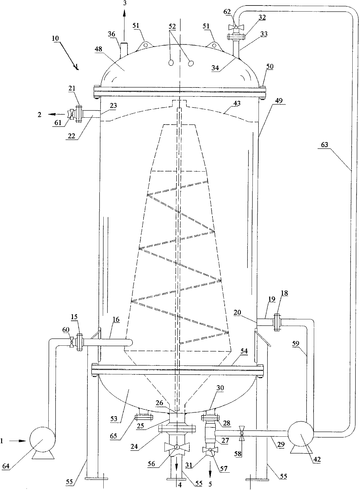
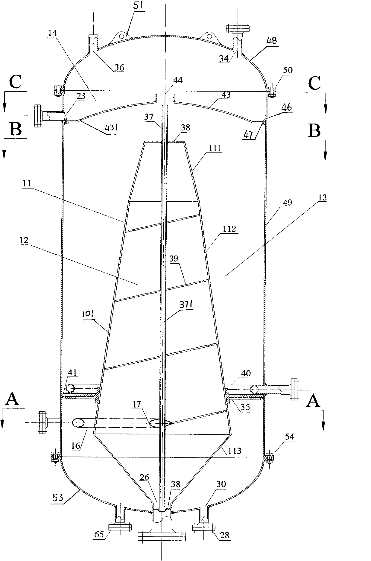
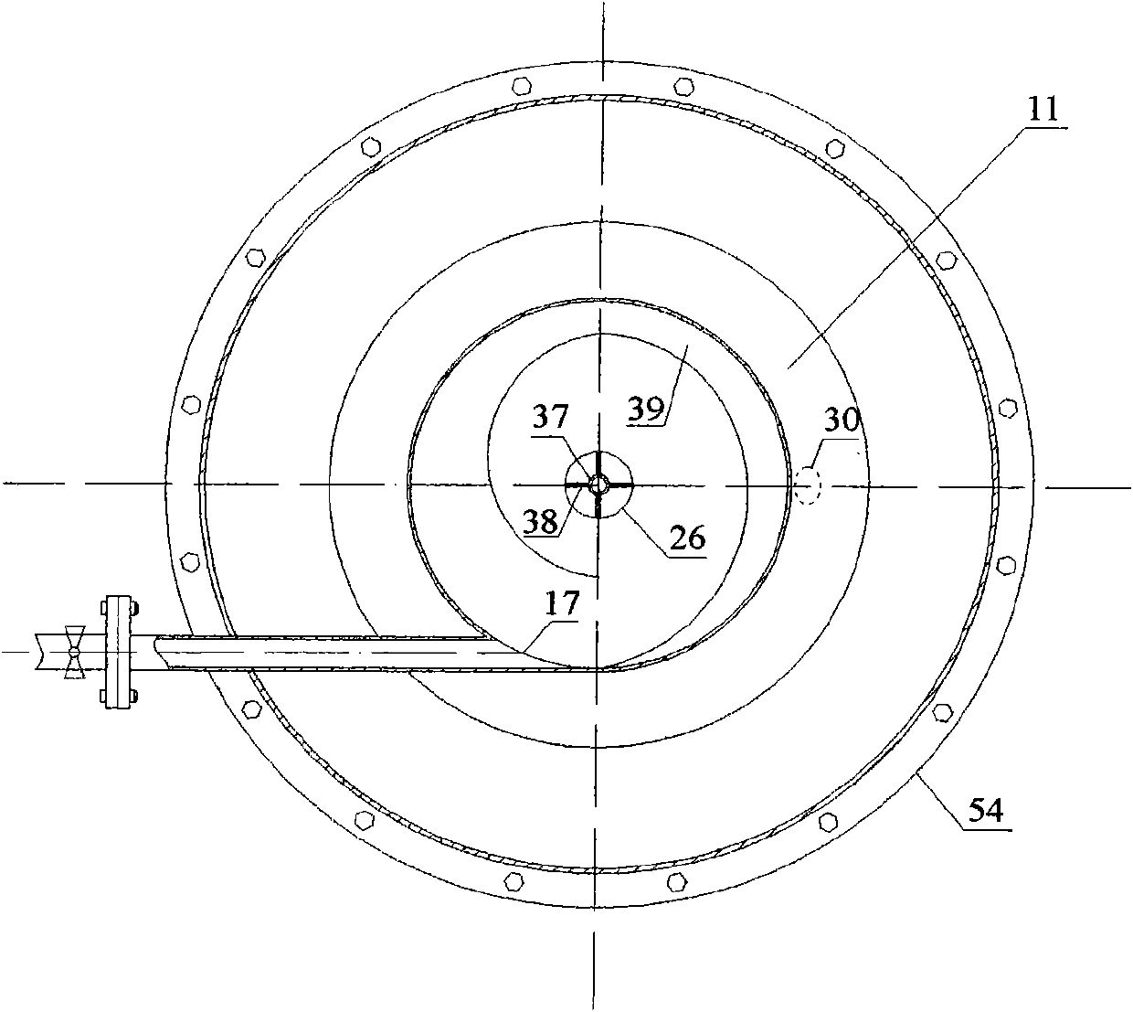
[0025] Depend on Figure 1 to Figure 6 Shown is a multiphase separation system for oily wastewater treatment, which is mainly composed of a swirling air flotation integrated separator 10, a multiphase flow pump 64 for gas-liquid mixing at the inlet of oily wastewater, and a multiphase flow pump 64 for mixing partly recirculated purified water and circulating gas. Phase flow pump 42 and necessary pipelines and valves, in which: cyclone air-flotation integrated separator 10 is fixed on the ground through three legs 55, an oval upper head 48 is set on the upper part, and a cylindrical shell 49 is set in the middle , the lower part is provided with an elliptical lower head 53, which is provided with an arc-shaped oil collection cover 43, a conical swirl tube 11, an anti-vortex air duct 37, an annular water distributor 40 and an annular baffle 35, and the arc-shaped oil collection cover 43 is located at the upper part of the separator and the annular water distributor 40 and the an...


PUM


Abstract

The invention discloses a multiphase separation method and a system for processing oily waste water. The multiphase separation system comprises a cyclone-air flotation integrated separator, a multiphase pump for mixing gas with liquid arranged at an oily waste water inlet, a multiphase pump for mixing pure water for circulation and backflow with circulation gas and the like. The oily waste water enters from the bottom of a tank body into a cyclone to perform a hydrocyclone separation, tiny bubbles in the waste water are released to perform a first air floatation, light substances such as bubbles with oil particles are moved to the top of the cone-shape cyclone, heavy substances such as solid particles are moved to the bottom of the cone-shape cyclone, the waste water runs over the top of the cone-shape cyclone to enter a secondary air floatation zone, the pure water for circulation and backflow and circulation gas are shear mixed in the multiphase pump, then the oily waste water is subject to a secondary air floatation by using gas-liquid mixture from water distributing apertures on an annular water-locator, and the waste water is subject to a hydrocyclone separation and two air floatation separations in a separator. The invention has the advantages of simple and compact structure, high work efficiency, and is used for the purifying process of oily waste water containing tiny dispersed oil particles.

Description

technical field [0001] The invention relates to a method and equipment for separating multiphase mixed media such as oil, gas, water, solid suspended matter and even sand grains, and is especially suitable for purifying and treating oily wastewater containing tiny dispersed oil particles. Background technique [0002] Oily wastewater is often encountered in petroleum and petrochemical industries, machinery manufacturing, and urban life, and the removal of oil is often the primary treatment task. There are many methods for oil-water separation. The commonly used methods include gravity sedimentation, centrifugal sedimentation, air flotation, coagulation filtration, adsorption, membrane separation, etc. Each treatment method has its own advantages and disadvantages and specific scope of application. Among them, the air flotation method has mature technology, low cost and large treatment capacity, and can effectively remove emulsified oil and partially soluble pollutant compone...

Claims


Application Information

Patent Timeline
IPC IPC(8): C02F9/02C02F1/38C02F1/24
Inventor 陈家庆韩旭王莹莹
Owner BEIJING INSTITUTE OF PETROCHEMICAL TECHNOLOGY
Learn More