Supercharge Your Innovation With Domain-Expert AI Agents!

Data collecting method for X-Y galvanometer scanning ultra-spectral image

A technology of galvanometer scanning and acquisition methods, which is applied in spectrometry/spectrophotometry/monochromator, absorption/scintillation/reflection spectroscopy, spectrum investigation, etc., which can solve the problem of large mechanical structure and cost of the push-broom system. High, small scanning field of view and other issues, to achieve the effect of large scanning field of view, low cost, and simple structure

Inactive Publication Date: 2011-09-28
TIANJIN UNIV
View PDF5 Cites 5 Cited by
  • Summary
  • Abstract
  • Description
  • Claims
  • Application Information

AI Technical Summary

Problems solved by technology

[0005] Although the area array push-broom method has achieved good results in various fields, the push-broom system has the disadvantages of large overall mechanical structure, high cost, and small scanning field of view.

Method used


Image

  • Data collecting method for X-Y galvanometer scanning ultra-spectral image
  • Data collecting method for X-Y galvanometer scanning ultra-spectral image
  • Data collecting method for X-Y galvanometer scanning ultra-spectral image

Examples


Embodiment 1

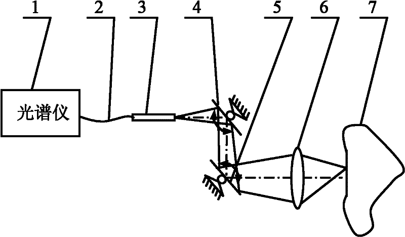
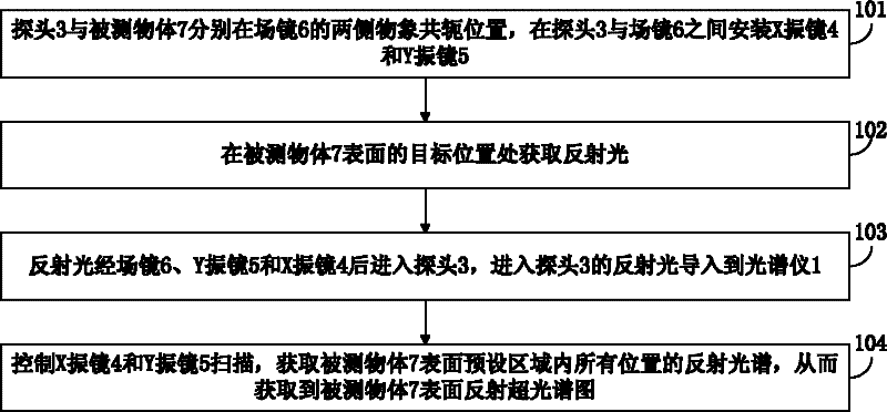
[0045] Embodiment 1: as figure 1 As shown, the probe 3 and the measured object 7 are respectively at the object image conjugate positions on both sides of the field mirror 6, and the X galvanometer 4 and the Y galvanometer 5 are installed between the probe 3 and the field mirror 6; the external illumination light is on the measured object 7 Reflection occurs at the target position on the surface to obtain reflected light; the reflected light enters the probe 3 after passing through the field mirror 6, Y galvanometer 5 and X galvanometer 4, and the reflected light entering the probe 3 is introduced into the spectrometer 1 through the optical fiber 2; the spectrometer 1 pairs The reflected light is sampled to obtain the reflection spectrum; by controlling the X galvanometer 4 and the Y galvanometer 5, the reflection spectrum of all positions in the preset area on the surface of the measured object 7 is obtained, thereby obtaining the surface reflection hyperspectral map of the me...

Embodiment 2

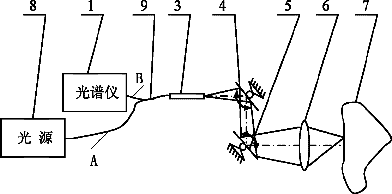
[0046] Embodiment 2: as figure 2 As shown, the probe 3 and the measured object 7 are respectively at the image conjugate positions on both sides of the field mirror 6, and the X vibrating mirror 4 and the Y vibrating mirror 5 are installed between the probe 3 and the field mirror 6; the light source 8 passes through the Y-shaped optical fiber 9 The A end enters the probe 3, the X vibrating mirror 4, the Y vibrating mirror 5 and the field mirror 6 and illuminates the target position on the surface of the measured object 7, and reflection occurs at the target position to obtain reflected light; the reflected light passes through the field mirror 6, Y vibrating The mirror 5 and the X vibrating mirror 4 enter the probe 3, and the reflected light entering the probe 3 is introduced into the spectrometer 1 through the B end of the Y-shaped optical fiber 9; the spectrometer 1 samples the reflected light to obtain the reflection spectrum; by controlling the X vibrating mirror 4 and Th...


PUM


Abstract

The invention discloses a data collecting method for an X-Y galvanometer scanning ultra-spectral image, relating to the data collecting for ultra-spectral images. The method disclosed by the invention comprises the following steps: a probe and a to-be-measured object are placed on the two sides of the field lens respectively and in conjugate positions, and a galvanometer X and galvanometer Y are arranged between the probe and field lens; the reflected light is obtained at the target position on the measured object surface; the reflected light enters into the probe through the field lens, galvanometer X and galvanometer Y and is led into the spectrograph; the galvanometer X and galvanometer Y are controlled to scan so as to obtain the reflection spectrum including all positions in the pre-set areas on the measured object surface so as to get the reflection ultra-spectral image of the measured object surface. The invention has the advantages of simple and stable mechanical system, large scanning field, high resolution, good practicability and low costs.

Description

technical field [0001] The invention relates to the collection of hyperspectral data, in particular to an X-Y galvanometer scanning type hyperspectral data collection method, which has the advantages of simple structure, large scanning field of view, stable system, high spectral resolution, strong practicability and low cost. low feature. Background technique [0002] Hyperspectral technology is a technology that integrates light, mechanics, electricity and computers. It can simultaneously image the same target on a continuous spectrum segment, and can directly reflect the spectral characteristics of the observed object, and even the material composition of the object surface, so it has extremely high application value in military, industrial, agricultural, medical and other fields. [0003] The current hyperspectral technology is divided into two types according to the scanning method: rotary scanning and area array push-broom. Among them, the collection system of the rot...

Claims


Application Information

Patent Timeline
Patent Type & Authority Applications(China)
IPC IPC(8): G01J3/42G01J3/02
Inventor 李刚赵静林凌
Owner TIANJIN UNIV
Features
  • R&D
  • Intellectual Property
  • Life Sciences
  • Materials
  • Tech Scout
  • Unparalleled Data Quality
  • Higher Quality Content
  • 60% Fewer Hallucinations
Learn More