Welding belt bonding device of solar module

A solar module and bonding device technology, applied in photovoltaic power generation, sustainable manufacturing/processing, electrical components, etc., can solve problems such as shortened life, difficult separation, and inability to apply solar cells to solar modules, to prevent position changes, The effect of improving versatility

Inactive Publication Date: 2011-09-28
ARON SA
View PDF5 Cites 11 Cited by
  • Summary
  • Abstract
  • Description
  • Claims
  • Application Information

AI Technical Summary

Problems solved by technology

[0013] However, when the heating bonding part 4 is moved downward for bonding after the ribbon R is removed from the clamp 6, the position of the ribbon R during the process of removing the ribbon R from the clamp 6 may change. change, so there is a problem that the ribbon R cannot be bonded at the exact position
[0014] The welding ribbon R should be accurately placed on the bus line arranged on the upper part of the solar battery sheet 3. When the welding ribbon R is inconsistent with the bus line, the problems of low efficiency and shortened life of the solar battery sheet will be caused.
[0015] In addition, after bonding the above-mentioned ribbon R, the ribbon R is separated from the tongs 6, and the heated ribbon R is fused to the tongs 6, making it difficult to separate, or the tongs 6 leave a residue of the ribbon R. object, so that a good clamping of the ribbon R cannot be formed afterwards
[0016] At the same time, in the existing ribbon bonding device for solar modules, the distance from the ribbon supply part 1 for supplying the ribbon to the heating bonding part 4 is fixed, so it is difficult to apply it to solar modules in other application fields. Adhesive Ribbon on Module
[0017] That is, compared with the spacing between the solar cells of the usual solar module, the distance between the solar cells of the solar module suitable for glass windows or building integrated photovoltaic (Building Integrated Photovoltaic System) is larger, so as to improve the transparency. However, the position of the heating bonding part 4 of the ribbon bonding device of the existing solar module is fixed, so it cannot be applied to solar modules with various spacings between solar cells

Method used


Image

  • Welding belt bonding device of solar module
  • Welding belt bonding device of solar module
  • Welding belt bonding device of solar module

Examples


Embodiment Construction

[0036] Hereinafter, preferred embodiments of the solar module ribbon bonding apparatus of the present invention configured as above will be described in detail with reference to the drawings.

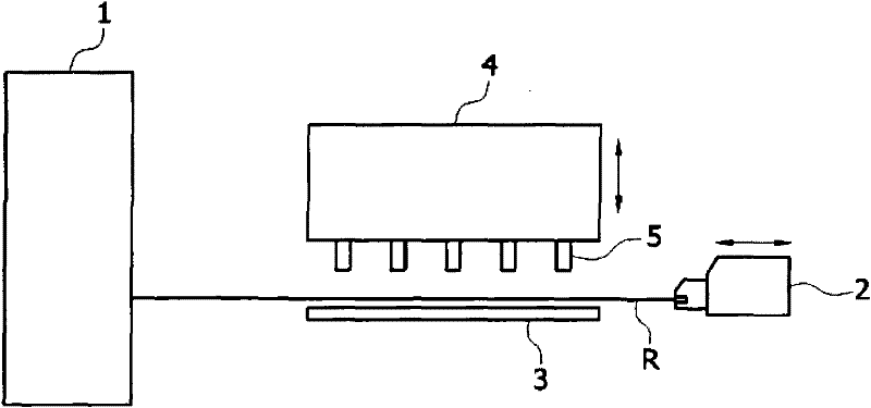
[0037] figure 2 is a configuration diagram of a ribbon bonding device for a solar module according to a preferred embodiment of the present invention.

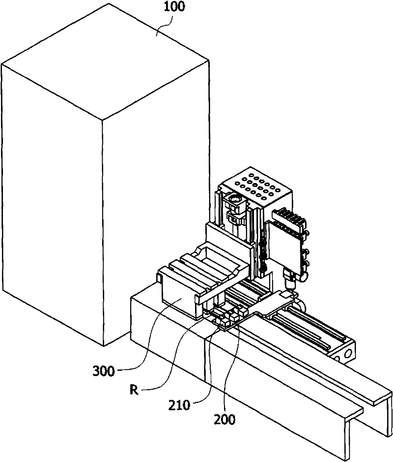
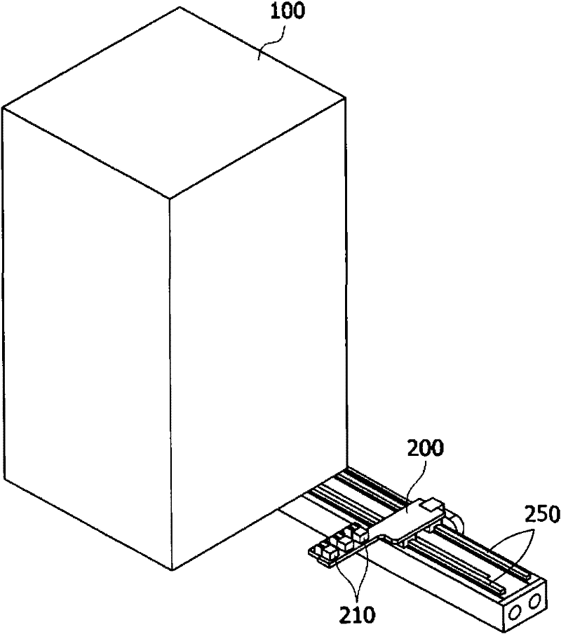
[0038] refer to figure 2 According to the preferred embodiment of the present invention, the ribbon bonding device for solar modules includes: ribbon supply part 100, used to supply ribbon (ribbon) R; loader 200, clamped by clamp 210 and drawn out The ribbon R supplied by the ribbon supply part 100 is provided with a separation part 220 arranged at the front end of the clamp 210 to separate the ribbon R when the clamp 210 is opened; The welding ribbon R drawn out by the machine 200 is bonded to the solar battery sheet, and according to the separating part 220 , the welding ribbon R is fixed when the welding ribbon R is detached from...


PUM


Abstract

The invention relates to a welding belt bonding device of a solar module, comprising a loading machine which clamps and leads out the welding belt supplied by a welding belt supply portion, enabling the welding belt to pass the upper part of a solar cell, and a heating bonding portion which is provided with a plurality of first pins in the bottom to prevent the led-out welding belt from displacing under the state of clamping release. The welding belt under the state of clamping release is fixed and bonded to the solar cell by means of the first pins and a plurality of second pins protruding the bottom face. The welding belt is fixed to a bus of the solar cell by means of pins whose height of the tail ends are shorter among all the pins, and a component enabling the welding belt to completely disengage from a clamp is provided. Therefore, the position of the welding belt can be prevented from changing and bonding can be conducted at a correct position. The effect of preventing the solar module from having a low efficiency and preventing the service lifetime from being shortened can be achieved.

Description

technical field [0001] The invention relates to a welding ribbon bonding device for a solar module, in particular to a device that can prevent the welding ribbon from swaying when the welding ribbon is loaded on the upper part of the solar battery sheet, and prevent the welding ribbon from being welded to the solar module of the loader from sticking. knot device. Background technique [0002] Generally, solar cells used for solar power generation can generate electricity when they are in the form of solar cells based on silicon materials or various compounds. However, since sufficient power cannot be obtained with one cell, it is necessary to connect each cell in series or in parallel, and the solar cells connected in this way are called "solar modules." [0003] A solar module is composed of a back sheet, solar cells, ribbon, ethylene-vinyl acetate copolymer (EVA), and glass. The backplane is the material at the bottom of the module, and polyvinyl fluoride composite film ...

Claims


Application Information

Patent Timeline
Patent Type & Authority Applications(China)
IPC IPC(8): H01L31/18H01L31/042
CPCY02E10/50Y02P70/50H01L31/188
Inventor 郑相国李光哲
Owner ARON SA
Why Eureka
Try Eureka