Digital pulsed ultrasound transmitting device for fetal monitor

An ultrasonic emission and digital pulse technology, applied in the field of medical devices, can solve the problems of high noise, difficult to detect fetal heart signals, low sensitivity, etc., and achieve the effects of increasing the capture range, easy fetal heart capture, and strong anti-interference ability.

Inactive Publication Date: 2011-10-12
泰安市迈迪医疗电子有限公司
View PDF6 Cites 9 Cited by
  • Summary
  • Abstract
  • Description
  • Claims
  • Application Information

AI Technical Summary

Problems solved by technology

The ultrasonic transmission frequency used by most monitors is between 2.0MHz and 2.5MHz, which is relatively high, because the attenuation of ultrasonic waves in the human body is proportional to the frequency of ultrasonic waves, so when ultrasonic waves of a certain intensity and higher frequency propagate, there are the following Question: ①If the propagation distance is the same, the higher the frequency, the greater the attenuation, the weaker the reflected echo, the lower the sensitivity, and the less likely it is to detect the fetal heart signal; ②The higher the frequency, the greater the attenuation, and the effective transmission of ultrasonic waves the shorter the distance
[0005] 1) The sound beam of the ultrasonic probe is thin, the fetal heart rate capture range is narrow, and it is easily affected by fetal m

Method used


Image

  • Digital pulsed ultrasound transmitting device for fetal monitor
  • Digital pulsed ultrasound transmitting device for fetal monitor
  • Digital pulsed ultrasound transmitting device for fetal monitor

Examples


Embodiment Construction

[0023] The present invention is described in detail below in conjunction with accompanying drawing and specific embodiment:

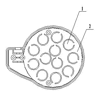
[0024] Such as figure 1 and figure 2 A specific embodiment of the invention is shown.

[0025] Such as figure 1 As shown, the ultrasonic probe includes 8-12 chips 1 evenly arranged on the radiation surface 2 of the probe. The chip 1 integrates the functions of transmitting and receiving signals, has the same diameter of 12 mm, and the ultrasonic transmitting frequency is 1.0 MHz.

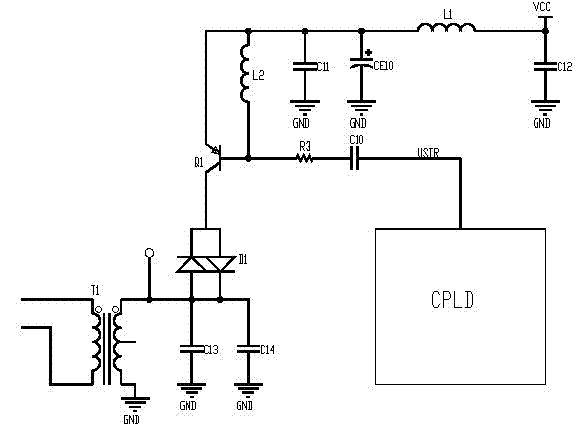
[0026] Such as figure 2 As shown, the ultrasonic transmitting circuit is composed of a digital integrated circuit module CPLD and a transmitting circuit. The transmitting circuit is a resonant amplifier circuit and its peripheral circuits. In the resonant circuit, the inductor L2 is connected between the base and the emitter of the triode Q1. C14. After the transformer T1 is connected in parallel, one end is grounded, and the other end is connected to the collector of t...


PUM


Abstract

The invention discloses a digital pulsed ultrasound transmitting device for a fetal monitor, relating to the field of medical equipment. The digital pulsed ultrasound transmitting device comprises an ultrasound probe and an ultrasound transmitting circuit which are connected with each other, wherein the ultrasound probe employs a plurality of wafers which integrates transmission and reception functions into a whole and has the transmitting frequency of 1.0 MHz, the wafers are arranged on the radiation surface of the probe uniformly. The digital pulsed ultrasound transmitting device has wide ultrasound transmission acoustic beams, and is hardly affected by fetal movement and uterine contraction during detection upon a fetal heart signal in a monitoring process, so that the monitoring result is more accurate and reliable; the transmitting circuit generates a transmission electric excitation square wave signal of 1.0 MHz by using a CPLD (Complex Programmable Logic Device) digital circuit, the transmission electric excitation square wave signal is coupled to the ultrasonic probe by a resonant amplification circuit so as to generate an ultrasonic wave of 1.0 MHz; and the digital pulsed ultrasound transmitting device is low in transmission frequency, less in attenuation in an ultrasound propagation process, strong in reflection echo, high in flexibility, low in noise, strong in anti-interference ability, and steady and reliable in performance.

Description

technical field [0001] The invention relates to the field of medical instruments, in particular to a digital pulsed ultrasonic emitting device for fetal monitors. Background technique [0002] At present, most fetal monitors use 2.0MHz~2.5MHz continuous ultrasonic Doppler method to pick up fetal heart signal. The ultrasonic probe structure is a chip in the middle, with a diameter of 2cm, which emits ultrasonic waves. The width of the emitted ultrasonic beam is 2~3cm. , This is also the capture range of the fetal heart rate. The surrounding 6 small chips receive ultrasonic waves, and the fetal heart rate signals picked up are processed and displayed or printed. The ultrasonic transmission frequency used by most monitors is between 2.0MHz and 2.5MHz, which is relatively high, because the attenuation of ultrasonic waves in the human body is proportional to the frequency of ultrasonic waves, so when ultrasonic waves with a certain intensity and higher frequency propagate, there ...

Claims


Application Information

Patent Timeline
IPC IPC(8): A61B8/02
Inventor 范世忠
Owner 泰安市迈迪医疗电子有限公司
Why Eureka
Try Eureka