Compressed-air energy-storage system

A compressed air energy storage and compressor technology, which is applied in wind power generation, energy storage, solar thermal power generation, etc., can solve the problems of reduced operating efficiency, poor application characteristics under variable working conditions, and low efficiency of compressors and turbines, etc. Achieve the effect of improving flexibility, improving work efficiency, and optimizing configuration

Active Publication Date: 2011-10-12
中科国风科技有限公司
View PDF5 Cites 49 Cited by
  • Summary
  • Abstract
  • Description
  • Claims
  • Application Information

AI Technical Summary

Problems solved by technology

[0003] Although the compressed air energy storage system using thermal storage makes better use of energy and is environmentally friendly, the system has poor characteristics for variable duty applications
This is because compressed air energy storage is a large-scale energy storage method. The pressure of the air storage chamber, the size of the stored energy, the type and connection mode of the turbomachinery, etc. have been determined during the system design, which makes the system When working near the design conditions, there is the best work efficiency, and when the energy storage requirements deviate greatly from the design conditions, since the original system configuration cannot be changed, especially the connection mode of the compressor and the turbine, the compressed gas The efficiency of the machine and turbine is not high, and the overall operating efficiency of the system will be reduced
[0004] Therefore, for the problem of the poor flexibility of the compressed air energy storage system using thermal storage, especially the optimal configuration of the compressor and turbine under different working conditions, a reasonable solution must be found in order to make the compressed air energy storage The system can be used more widely and effectively

Method used


Image

  • Compressed-air energy-storage system
  • Compressed-air energy-storage system
  • Compressed-air energy-storage system

Examples


Embodiment 1

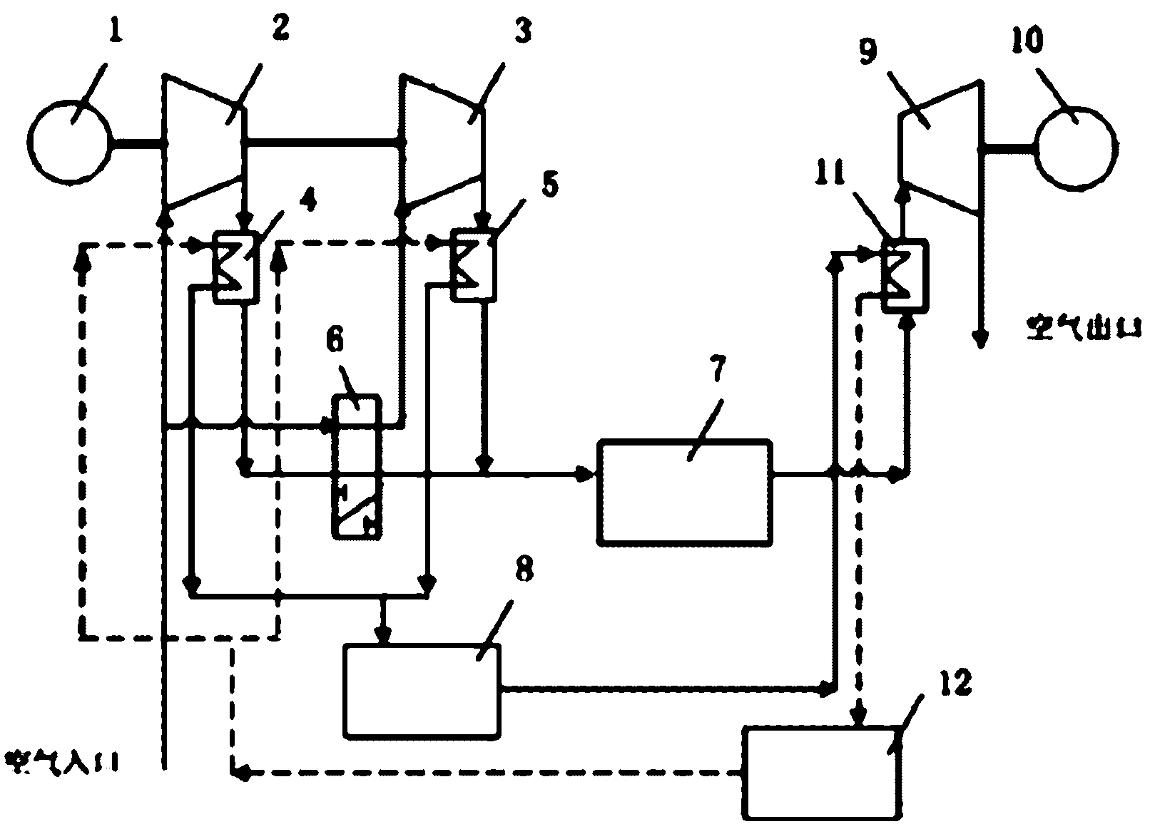
[0032] Such as figure 1 As shown, a compressed air energy storage system includes: an electric motor 1, a low-pressure stage compressor 2, a high-pressure stage compressor 3, a low-pressure stage cooler 4, a high-pressure stage cooler 5, an air storage chamber 7, a thermal storage 8, at least A turbine 9, a generator 10, at least one heat exchanger 11, a cooling medium supply source 12, the electric motor 1 is fixedly connected to the common transmission shaft of the low-pressure compressor 2 and the high-pressure compressor 3, the generator 10 and the turbine The transmission shaft of machine 9 is fixedly connected; the hot-side inlets of low-pressure stage cooler 4 and high-pressure stage cooler 5 are respectively connected with the gas outlets of low-pressure stage compressor 2 and high-pressure stage compressor 3, and the hot-side outlet is connected with gas storage chamber 7 The inlet of the low-pressure stage cooler 4 and the high-pressure stage cooler 5 are connected wit...

Embodiment 2

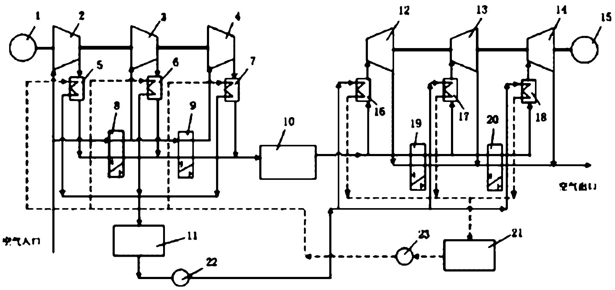
[0035] Fig. 2 is a schematic diagram of the compressed air energy storage system of "Embodiment 2" of the present invention. The compressed air energy storage system includes: electric motor 1, low-pressure compressor 2, medium-pressure compressor 3, high-pressure compressor 4, low-pressure cooler 5, medium-pressure cooler 6, high-pressure cooler 7, three One-position four-way valve Ⅰ8, three-position four-way valve II9, gas storage chamber 10, heat storage 11, high-pressure stage turbine 12, medium-pressure stage turbine 13, low-pressure stage turbine 14, generator 15, high-pressure stage Heat exchanger 16, medium-pressure heat exchanger 17, low-pressure heat exchanger 18, three-position four-way valve III19, three-position four-way valve IV20, cooling medium supply source 21, power pump I22, power pump II23. The difference between this embodiment and Embodiment 1 is that three-stage compression is used in the energy storage stage, and three-stage expansion is used in the exp...


PUM


Abstract

The invention relates to a compressed-air energy-storage system. A three-position four-way valve is arranged in a pipeline of a compression part and an expansion part of the system and the flowing condition of air in the system is changed by utilizing the feature of change of a turn-on state of the three-position four-way valve, thus the variation of the manners of serial-connection and parallel-connection between a gas compressor and a turbine is realized, and the overall working efficiency is increased. With the adoption of the three-position four-way valve, on one hand, the overall flexibility of the compressed-air energy-storage system is improved, so that the operating of the system is more targeted, and the use of the compressed-air energy-storage system matched with various types of power stations is facilitated; and on the other hand, the service condition of turbomachinery is improved, and the optimized configuration of the turbomachinery according to the needs of energy storage and power generation can be realized.

Description

technical field [0001] The invention relates to the technical field of energy storage, in particular to a compressed air energy storage system which utilizes a three-position four-way valve to realize optimal configuration of turbomachinery. Background technique [0002] The traditional compressed air energy storage system is an energy storage system based on gas turbine technology. However, because countries around the world have put forward higher requirements for fuel utilization and environmental protection, some scholars at home and abroad have launched technical improvements to compressed air energy storage systems. Among them, the compressed air energy storage system using thermal storage is a relatively advanced energy storage method in the current energy storage technology. Heat, and heat the low-temperature and high-pressure compressed air during the work stage of the system to increase the output work of the turbine. [0003] Although the compressed air energy s...

Claims


Application Information

Patent Timeline
Patent Type & Authority Applications(China)
IPC IPC(8): F01D15/10F01K3/08F03D9/02F03G6/00F03D9/17
CPCY02E10/46Y02E10/72Y02E70/30
Inventor 杨科张远李雪梅徐建中
Owner 中科国风科技有限公司
Why Eureka
Try Eureka