Mechanical work drive-free absorption type thermal converter

A heat exchanger and absorption technology, which is applied in the field of absorption heat pump and low-grade energy utilization, can solve the problems affecting the reliability of the solution system and limit the wide application of traditional absorption heat exchangers, and achieve good application prospects and simple structure , to avoid the effect of mechanical energy

Inactive Publication Date: 2011-10-12
ZHEJIANG UNIV
View PDF6 Cites 5 Cited by
  • Summary
  • Abstract
  • Description
  • Claims
  • Application Information

AI Technical Summary

Problems solved by technology

Traditional absorption heat exchangers that have been put into commercial use are mainly based on H 2 O / LiBr is the working fluid. Due to the high operating temperature of the mechanical solution pump and high sealing requirements, H 2 The strong corrosiveness of O / LiBr solution seriously affects the reliability of the solution system, which limits the wide application of traditional absorption heat exchangers

Method used


Image

  • Mechanical work drive-free absorption type thermal converter
  • Mechanical work drive-free absorption type thermal converter
  • Mechanical work drive-free absorption type thermal converter

Examples


Embodiment 1

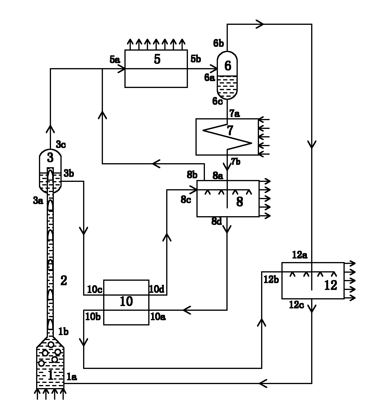
[0023] like figure 1 As shown, an absorption heat converter driven by no mechanical work includes: a generator 1, a riser 2, a first gas-liquid separator 3, a condenser 5, a second gas-liquid separator 6, an evaporator 7, a first An absorber 8 , a first regenerator 10 and a second absorber 12 .

[0024]Wherein, the feed port 1 a at the bottom of the generator 1 is connected to the absorbent outlet 12 c of the second absorber 12 , and the feed port 1 b at the top of the generator 1 is connected to the feed port at the bottom of the riser 2 . The discharge port at the top of the riser 2 is inserted into the cavity of the first gas-liquid separator 3 through the inlet end 3a at the bottom of the first gas-liquid separator 3, and the insertion height is greater than or equal to 1 / 2 of the total height of the inner cavity. The side wall of the top is sealed and fixed to the edge of the inlet end 3 a at the bottom of the first gas-liquid separator 3 . The liquid section liquid out...

Embodiment 2

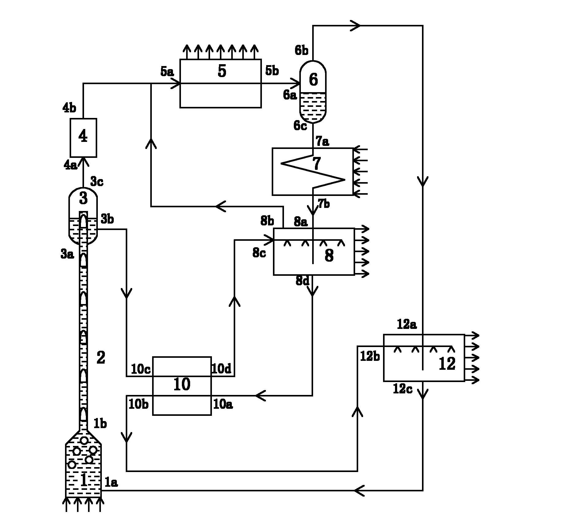
[0033] The structure is the same as in Example 1, except that a rectifying device is arranged between the first gas-liquid separator 3 and the condenser 5, for further removing the gas carried in the gas separated from the first gas-liquid separator 3 Small amount of absorbent.

[0034] The rectifying device 4 can be selected from a conventional fractionating column or other rectifying devices that can achieve the same function, and other parameters are selected with the same embodiment 1. Wherein, the feed port 4a of the rectification device 4 is connected with the gas outlet 3c of the gas section of the first gas-liquid separator 3 , and the feed port 4b of the rectification device 4 is connected with the inlet port 5a of the condenser 5 .

[0035] The absorbent collected in the rectification device 4 is returned to the first gas-liquid separator 3 along the pipeline between the first gas-liquid separator 3 and the rectification device 4, and the purified mixed refrigerant H...

Embodiment 3

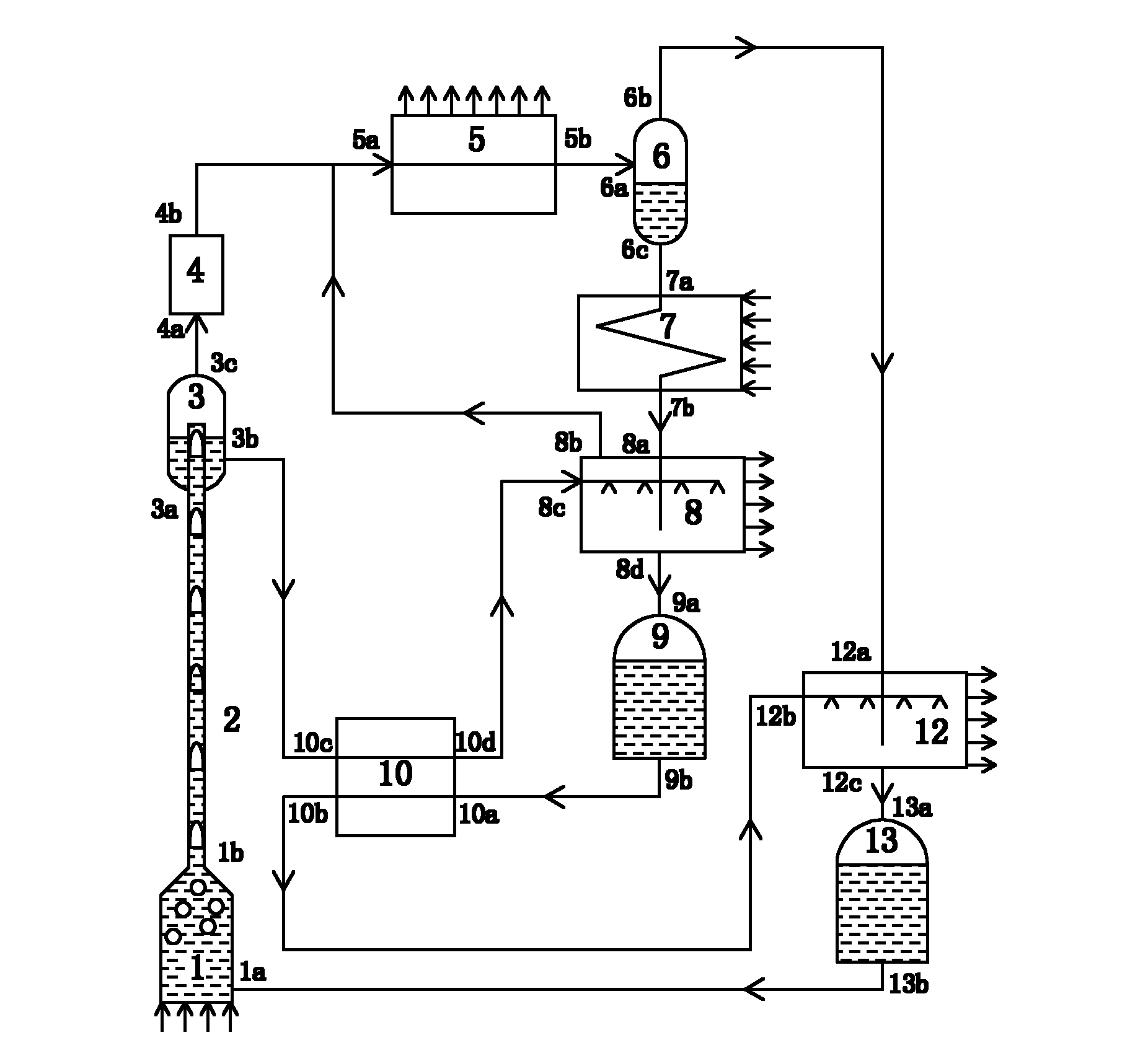
[0037] The rest of the structure is the same as that of Embodiment 2, except that a first liquid reservoir 9 is provided between the first absorber 8 and the first regenerator 10, and a first liquid reservoir 9 is provided between the second absorber 12 and the generator. There is a second reservoir 13 to further increase the stability of the system operation.

[0038] The first liquid accumulator 9 and the second liquid accumulator 13 can be selected from commonly used liquid accumulators in refrigeration systems. During installation, it must be ensured that the liquid level in the first liquid reservoir 9 is higher than the height of the absorbent inlet port 12b of the second absorber 12, and that the liquid level in the second liquid reservoir 13 is higher than the discharge port at the top of the generator 1 The height of 1b is to ensure that the refrigerant and absorbent circulate automatically under the action of gravity, avoiding the use of mechanical force. Wherein, t...


PUM


Abstract

The invention discloses a mechanical work drive-free absorption type thermal converter which comprises a generator, a lifting pipe, a first gas-liquid separator, a condenser, a second gas-liquid separator, an evaporator, a first absorber, a first heat return device and a second absorber that are sequentially connected, wherein the lifting pipe and the first gas-liquid separator are arranged between the generator and the condenser; the second gas-liquid separator is arranged between the condenser and the evaporator; and the first heat return device is arranged between the first gas-liquid separator and the first absorber. The absorption type thermal converter is basically isotonic and ensures that an absorbing agent solution and a large-boiling range mixing refrigerant are simultaneously pumped by adopting a thermally-driven bubble pump without using a mechanical solution pump and a refrigerant pump, thus electric energy is not completely consumed, and operation reliability is improved. The invention is especially suitable for occasions having abundant medium-low temperature thermal resource and power shortage and needing high-temperature heat, and has a better application prospect.

Description

technical field [0001] The invention belongs to the field of absorption heat pump and low-grade energy utilization, in particular to an absorption heat converter without mechanical work drive. Background technique [0002] Absorption heat exchanger, also known as absorption heat pump, can make full use of a large amount of industrial low-temperature waste heat generated in petrochemical, metallurgy, power and other industrial energy, so that it can be directly used by the production process after the grade is raised. . It can effectively utilize low-grade energy such as industrial waste heat, geothermal heat, and solar energy. In addition, the absorption heat exchanger can avoid the use of refrigerants that can damage the atmospheric ozone layer, so it is of great significance to energy saving and environmental protection. Traditional absorption heat exchangers that have been put into commercial use are mainly based on H 2 O / LiBr is the working fluid. Due to the high oper...

Claims


Application Information

Patent Timeline
Patent Type & Authority Applications(China)
IPC IPC(8): F25B15/00
CPCY02A30/27Y02B30/62
Inventor 王勤龚磊陈光明王江浦孙淑飞郝楠
Owner ZHEJIANG UNIV
Why Eureka
Try Eureka