Temperature control type 10G 80km SFP+ (enhanced 8.5 and 10 gigabit small form factor pluggable module) optical module with low power consumption

A technology of temperature control and low power consumption, which is applied in the coupling of optical waveguides, electromagnetic wave transmission systems, electromagnetic transceivers, etc., can solve problems such as difficulty in adapting to requirements, and achieve good high-frequency debounce characteristics, overall performance optimization, and performance stable effect

Active Publication Date: 2011-10-12
INNOLIGHT TECHNOLOGY (SUZHOU) LTD
7 Cites 26 Cited by

AI-Extracted Technical Summary

Problems solved by technology

Traditional optical modules with separate lasers and detectors have be...

Method used

In summary, the temperature-controlled low power consumption 10G 80km SFP+ optical module of the present invention has superior performance, novel design, high-speed photoelectric conversion function, high integration, low power consumption, small size, stable performance, and high efficiency Low power consumption optical transmitting and receiving components. The optical receiving component adopts high-sensitivity ROSA, which is suitable for long-distance transmission of data by the optical module. It has high-speed photoelectric conversion function. The stability of the module optimizes the overall performance of the module. This design integrates novelty, practicability and creativit...

Abstract

The invention relates to a temperature control type 10G 80km SFP+ (enhanced 8.5 and 10 gigabit small form factor pluggable module) optical module with low power consumption, wherein a power supply unit is respectively connected with an optical transmit unit, an optical receiving unit, a digital diagnosis unit and a 20PIN electrical interface unit; the optical receiving unit is connected with the 20PIN electrical interface unit, converts input optical signals into electrical signals and outputs the electrical signals; the optical transmit unit is connected with the 20PIN electrical interface unit, converts the input electrical signals into optical signals and outputs the optical signals; the optical transmit unit is cooled by a TEC (Thermal Electrical Cooler); the optical transmit unit is connected with the optical receiving unit and the digital diagnosis unit and provides optical detection signals; and the digital diagnosis unit is connected with the 20PIN electrical interface unit and provides digital diagnosis signals to remote communication equipment. An optical receiving component adopts a high-sensitivity ROSA (Receiver Optical Subassembly) and adjusts the back bias voltage of an avalanche photo diode (APD) at different temperatures by utilizing an adjustable booster circuit so as to be suitable for the high-speed photoelectric conversion function of the optical module inthe long-distance transmission of the data; and the TEC is integrated in the optical module, thereby enhancing the stability of the module.

Application Domain

Technology Topic

Image

  • Temperature control type 10G 80km SFP+ (enhanced 8.5 and 10 gigabit small form factor pluggable module) optical module with low power consumption
  • Temperature control type 10G 80km SFP+ (enhanced 8.5 and 10 gigabit small form factor pluggable module) optical module with low power consumption
  • Temperature control type 10G 80km SFP+ (enhanced 8.5 and 10 gigabit small form factor pluggable module) optical module with low power consumption

Examples

  • Experimental program(1)

Example Embodiment

[0025] Design a temperature-controlled, long-distance low-power 10G 80km SFP+ optical module that meets the SFP+ protocol standard, high integration, simple circuit, low power consumption, small size, and high cost performance.
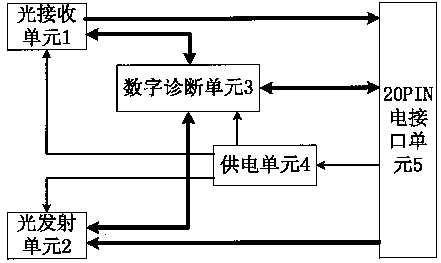
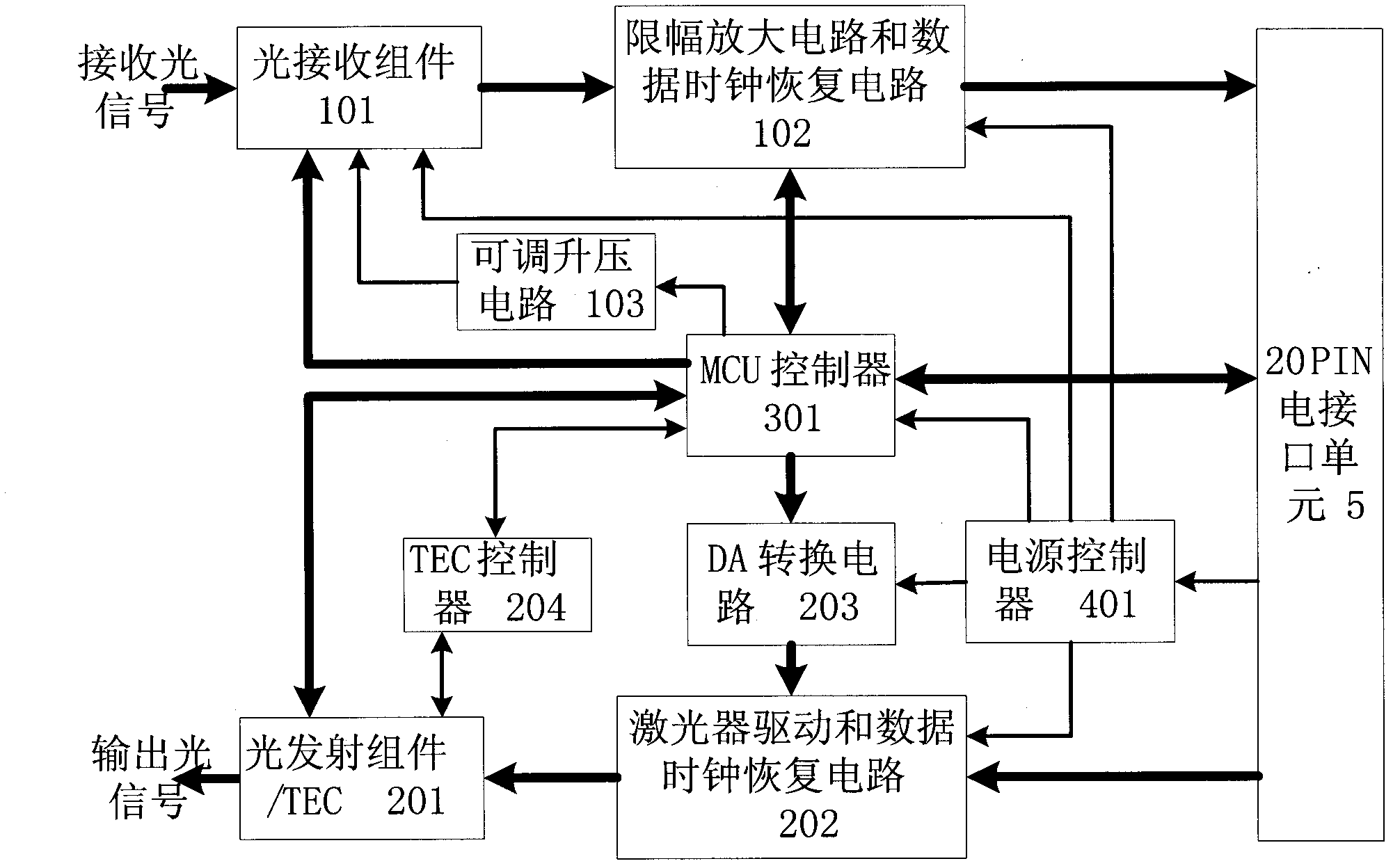
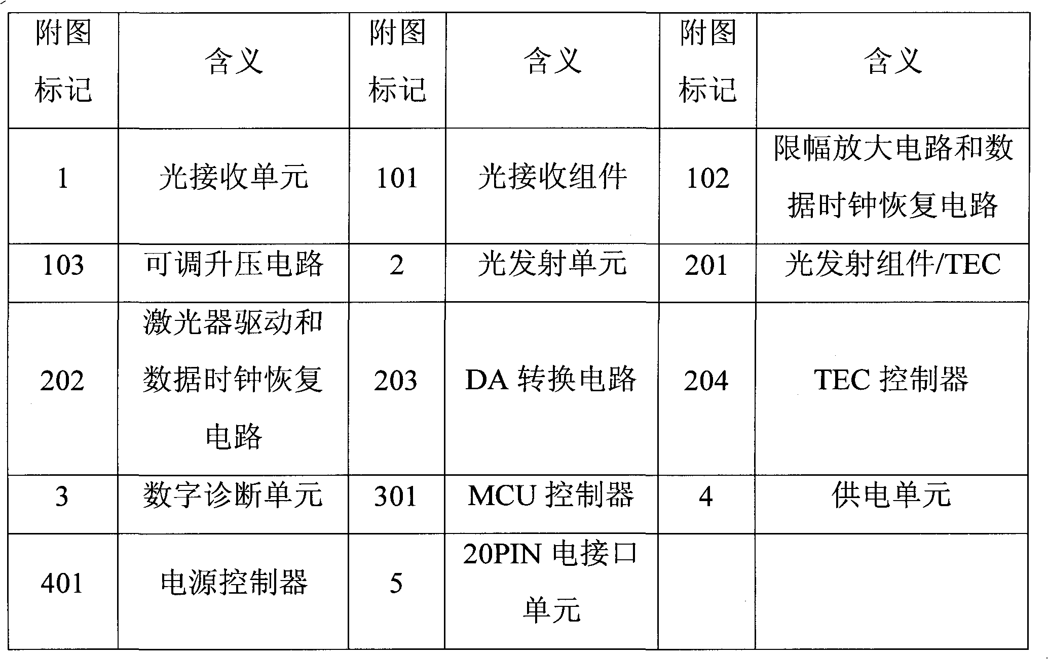
[0026] like figure 1 As shown, the temperature-controlled low-power 10G 80km SFP+ optical module includes an optical receiving unit 1, an optical transmitting unit 2, a digital diagnosis unit 3, a power supply unit 4, and a 20PIN electrical interface unit 5. The power supply unit 4 and the optical receiving unit 1 are respectively , light transmitting unit 2, digital diagnostic unit 3 and 20PIN electrical interface unit 5 are connected to provide power input; light receiving unit 1 is connected with digital diagnostic unit 3 to provide light detection signals; light transmitting unit 2 is connected to digital diagnostic unit 3 to provide The light detection signal; the light receiving unit 1 is connected with the 20PIN electrical interface unit 5, and the input optical signal is converted into an electrical signal for output; the light emission unit 2 is connected with the 20PIN electrical interface unit 5, and the input electrical signal is converted into an optical signal output, And the temperature of the light emission unit 2 is adjusted by the semiconductor refrigerator TEC; the digital diagnosis unit 3 is connected with the 20PIN electrical interface unit 5 to provide digital diagnosis signals to the remote communication equipment;
[0027] like figure 2 As shown, the light receiving unit 1 includes a light receiving component 101, a limiting amplifier circuit, a data clock recovery circuit 102 and an adjustable boost circuit 103. The light receiving component 101 adopts the ROSA produced by Gennum Company and the model is GN3352, so as to be suitable for For the long-distance transmission of data by the optical module, the optical receiving component 101 receives the optical signal from the optical synchronization network, converts it into an electrical signal, and transmits it to the limiting amplifier circuit and the data clock recovery circuit 102 after transimpedance amplification for data processing. Clock sampling and buffer processing, and transmit the converted signal to the 20PIN electrical interface unit 5;
[0028] The light emitting unit 2 includes a light emitting component/TEC 201, a laser driving and data clock recovery circuit 202, a DA conversion circuit 203 and a TEC controller 204, and the laser driving and data clock recovery circuit 202 receives the electrical signal input by the 20PIN electrical interface unit 5, Perform modulation and amplification processing, data clock sampling and buffer processing at the same time, and then send the electrical signal to the light emitting component/TEC201, while the semiconductor cooler TEC controls the temperature of the light emitting unit 2, and finally the light emitting component/TEC201 will input the electrical signal. The signal is converted into an optical signal and output to the synchronous optical network system; the light emitting component includes a laser diode LD and a monitoring photodiode PD, the laser diode LD is used to generate an optical signal, and the photodiode PD is used to monitor the luminous intensity of the laser diode LD;
[0029] The digital diagnosis unit 3 includes an MCU controller 301, the MCU controller 301 collects and processes module data and monitoring module data, and the internal memory of the MCU controller 301 stores module information and user information; the MCU controller 301 is used to transmit signals and user information to the optical module. Receive signal, power supply voltage and working temperature for data acquisition and processing, and send the data to remote computer and monitoring system; MCU controller 301 adopts advanced low-power microprocessor, which integrates memory, A/D converter, Communication module and data processing module, the internal memory is used to store module information and user information, the A/D converter is used for temperature detection, the communication module is used to communicate with external systems, and the data processing module is used for data processing and input signals. Monitor the light emitting unit;
[0030] The adjustable boost circuit 103 receives the signal from the MCU controller 301 and adjusts the reverse bias voltage of the avalanche photodiode (APD) in the light-receiving component at different temperatures, so that the light-receiving component reaches the optimum state at different temperatures.
[0031] The DA conversion circuit 203 converts the digital voltage signal output by the MCU controller 301 into an analog voltage signal, and sends it to the laser driving and data clock recovery circuit 202. The laser driving and data clock recovery circuit 202 sends the current signal into the optical signal according to the input of the analog voltage signal. Transmitting component/TEC201, driving it to emit light signal;
[0032] The TEC controller 204 monitors the temperature of the light emitting unit 2, and adjusts the temperature of the light emitting unit 2 by receiving the control signal output by the MCU controller 301;
[0033] The power supply unit 4 includes a power supply controller 401, which controls the opening and closing of each functional unit; the power supply controller 401 is composed of a field effect transistor and its peripheral circuits, and the gate of the field effect transistor is connected to the I/O of the MCU controller 301 through a resistive element. The O port is connected, and the MCU controller 301 controls the power on and off of the optical module.
[0034] The 20PIN electrical interface unit 5 provides the module power supply and the interface for communicating with the external system.
[0035] The optical transmitting unit 2 and the optical receiving unit 1 are integrated with a clock data recovery circuit, which has good high-frequency debounce characteristics, which is beneficial to the recovery of clock data during the transmission process of synchronous data in network communication. The light emitting unit 2 is integrated with a semiconductor cooler TEC. When the light emitting unit 2 is in an extreme temperature environment, stable optoelectronic characteristics, such as wavelength and optical power, can still be maintained, which improves the stability of signal transmission.
[0036] The temperature-controlled low-power 10G 80km SFP+ optical module complies with the "SFP+" optical module communication standard introduced by the industry, that is, the electrical interface is compatible with the "SFF-8031" standard, the optical interface is compatible with the "IEEE-802.3ae" standard, and the digital diagnostic function meets the "SFF-8031" standard. SFF-8472” standard, the volume meets the industry SFP+ optical module “SFF-8431” standard, the volume is: 56.4mm×13.7mm×8.5mm.
[0037] In specific applications, the external electrical modulation signal enters the optical module from the 20PIN electrical interface unit 5, and is sent to the laser driving and data clock recovery circuit 202, and is processed by the laser driving and data clock recovery circuit 202. The refrigerator TEC controls the temperature of the light emitting unit 2 , and the TEC controller 204 monitors the temperature change of the light emitting unit 2 and adjusts the temperature of the light emitting unit 2 by receiving the control signal output by the MCU controller 301 . The DA conversion circuit 203 provides a voltage signal to the laser driving and data clock recovery circuit 202 to generate corresponding bias current and modulation current, so that the light emitting component/TEC201 emits light and monitors its luminous intensity and working state, and simultaneously performs data clock sampling and buffering Then, the optical signal generated by the optical transmitting component/TEC 201 is transmitted to the optical network through the optical fiber; on the other hand, the optical signal in the optical network is transmitted to the optical receiving component 101 through the optical fiber, and undergoes photoelectric conversion and amplification processing and data clock sampling. After processing and buffering, the electrical signal is transmitted to the external system through the 20PIN electrical interface unit 5, and the adjustable boost circuit receives the signal from the MCU controller to adjust the reverse bias of the avalanche photodiode (APD) in the light receiving component at different temperatures. pressure, so that the light-receiving components can reach the best state at different temperatures. The MCU controller 301 adopts an advanced low-power microprocessor, which integrates memory, A/D converter, communication module and data processing module. The MCU controller 301 is used to transmit and receive signals to the optical module, supply voltage and work The temperature data is collected and processed, and the data is sent to the remote computer and monitoring system; the digital diagnosis unit 3 mainly provides digital diagnosis function for the optical module, so that it conforms to the "SFF-8472" protocol standard.
[0038] To sum up, the temperature-controlled low-power 10G 80km SFP+ optical module of the present invention has superior performance, novel design, high-speed photoelectric conversion function, high integration, low power consumption, small size, stable performance, and high efficiency and low power consumption. Light transmitting and receiving components, the light receiving components use high-sensitivity ROSA, which is suitable for the long-distance data transmission of the optical module and has high-speed photoelectric conversion function. The optical module integrates a semiconductor cooler (TEC), which improves the stability of the module. The overall performance of the module is optimized. The design integrates novelty, practicability and creativity. It is suitable for mass production and meets the needs of the synchronous optical network market.
[0039] It should be understood that: the above are only the preferred embodiments of the present invention, and for those skilled in the art, without departing from the principles of the present invention, several improvements and modifications can also be made. These improvements and Retouching should also be considered within the scope of protection of the present invention.

PUM

PropertyMeasurementUnit
Sensitivity26.0
tensileMPa
Particle sizePa
strength10

Description & Claims & Application Information

We can also present the details of the Description, Claims and Application information to help users get a comprehensive understanding of the technical details of the patent, such as background art, summary of invention, brief description of drawings, description of embodiments, and other original content. On the other hand, users can also determine the specific scope of protection of the technology through the list of claims; as well as understand the changes in the life cycle of the technology with the presentation of the patent timeline. Login to view more.

Similar technology patents

Classification and recommendation of technical efficacy words

  • Innovative design
  • Highly integrated

Catheter with bendable tip

Owner:BIOSENSE WEBSTER INC

Efficient broadband switching-mode amplifier

ActiveUS20050083122A1Innovative designPresent inventionPush-pull amplifiersPhase-splittersAudio power amplifierBroadband amplifiers
Owner:RAYTHEON CO

Vehicle power management system and control method thereof

ActiveCN106114426AHighly integratedIntegration is simple and easyElectric/fluid circuitWork statusAutomotive engineering
Owner:GUANGZHOU AUTOMOBILE GROUP CO LTD

Pulse width signal duty ratio detection circuit

ActiveCN101964647AImprove reliabilityHighly integratedPulse train pattern monitoringPhysicsCapacitance
Owner:NINGBO SEMICON INT CORP
Why Eureka
Try Eureka