Single-fiber bidirectional transceiver module and capsulation thereof

A technology of single-fiber bidirectional transceiver and installation end, which is applied to the coupling of optics, instruments, and optical waveguides, and can solve the problems of large volume of optical transceiver modules, conflicts, and large structural dimensions of single-fiber bidirectional components, achieving size reduction and area small effect

Inactive Publication Date: 2011-10-12
SOURCE PHOTONICS CHENGDU
View PDF6 Cites 17 Cited by
  • Summary
  • Abstract
  • Description
  • Claims
  • Application Information

AI Technical Summary

Problems solved by technology

This also makes the optical transceiver module require a larger volume, resulting in a larger structural size of the single-fiber bidirectional component, which conflicts with the small-size package of SFP+

Method used


Image

  • Single-fiber bidirectional transceiver module and capsulation thereof
  • Single-fiber bidirectional transceiver module and capsulation thereof
  • Single-fiber bidirectional transceiver module and capsulation thereof

Examples


Embodiment 1

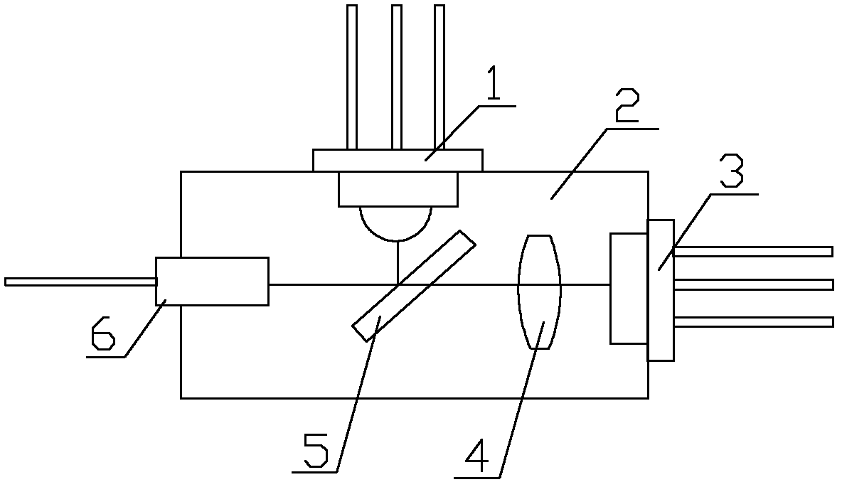
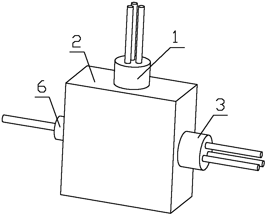
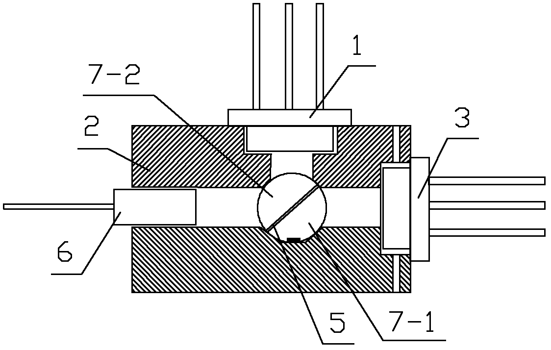
[0062] See figure 2 with image 3 The single-fiber bidirectional transceiver module shown includes a first hemispherical lens 7-1, a second hemispherical lens 7-2, and a beam splitter 5. The beam splitter 5 is arranged at an inclination angle of 45° in the optical path. The first hemispherical lens 7-1, The second hemispherical lens 7-2 and the beam splitter 5 are combined into a sphere; the laser diode 3 is placed at the focal point of the first hemispherical lens 7-1, and the photodiode 1 is placed at the focal point of the second hemispherical lens 7-2 At; the lower end of the first ball lens 7-1 located below is provided with a positioning groove. Package 2 applied to the light-emitting module (such as Figure 7 (Shown), including the laser diode mounting end 2-2, the photodiode mounting end 2-4, and the optical fiber mounting end 2-5. The package 2 has a cavity 9 corresponding to the beam splitter 5 and the hemispherical lens; cavity 9 The lower wall of the cavity 9 is pr...

Embodiment 2

[0065] See figure 2 , Figure 4 The single-fiber bidirectional transceiver module shown includes a hemispherical lens 7-1, a hemispherical lens 7-2, and a beam splitter 5. The beam splitter 5 is arranged at an inclination angle of 45° in the optical path. The first hemispherical lens 7-1 and the second hemispherical lens The plane of 7-2 is arranged on both sides of the beam splitter 5 in a vertical state; the two ends of the beam splitter 5 are fixed with the first hemispherical lens 7-1 and the second hemispherical lens 7-2 by bonding. Both ends of 5 are in contact with the first hemispherical lens 7-1 and the second hemispherical lens 7-2 respectively, wherein the laser diode 3 is placed at the focal point of the first hemispherical lens 7-1, and the beam splitter 5 is placed in the second hemisphere The focal point of lens 7-2.

[0066] Package 2 applied to the light-emitting module (such as Picture 9 Shown), including the laser diode mounting end 2-2, the photodiode mounti...

Embodiment 3

[0068] See figure 2 , Figure 5 , Picture 12 The single-fiber bidirectional transceiver module shown includes a hemispherical lens 7-1, a hemispherical lens 7-2, and a beam splitter 5. The beam splitter 5 is arranged at an inclination angle of 45° in the optical path. The first hemispherical lens 7-1 and the second hemispherical lens The plane of 7-2 is arranged on both sides of the beam splitter 5 in a vertical state; both ends of the beam splitter 5 and the first hemispherical lens 7-1 and the second hemispherical lens 7-2 are fixed in one body by a rectangular frame 10, The laser diode 3 is placed at the focal point of the first hemispherical lens 7-1, and the beam splitter 5 is placed at the focal point of the second hemispherical lens 7-2.

[0069] Package 2 applied to the light-emitting module (such as Picture 9 Shown), including the laser diode mounting end 2-2, the photodiode mounting end 2-4, and the optical fiber mounting end 2-5. The inside of the package 2 has a cav...


PUM


Abstract

The invention discloses a single-fiber bidirectional transceiver module which comprises a laser diode, a photodiode, a first lens and a second lens, wherein an optical splitter is arranged between the first lens and the second lens; the optical splitter is plated with an anti-reflection film and an anti-incidence film; and the first lens, the second lens, the laser diode and the photodiode have the same optical axis, and the optical axis is a straight line. The invention further discloses the capsulation for the module and an application method thereof. In the invention, the lens in the prior art and the hemispherical end surface of the photodiode are improved into the hemispherical lens or spherical lens in the direction of the laser diode, thereby reducing the dimension of an optical module in the direction of the laser diode and ensuring that multiple optical transceivers can be arranged on the circuit board with the same dimension or the same optical transceivers can be arranged; and the area of the circuit board is small, thereby enabling the dimension of the whole optical device to be reduced. In the invention, the focusing is carried out on optical signals by adopting the hemispherical lens or the spherical lens, thereby greatly enhancing the coupling ratio of the photodiode, the optical fiber and the optical path of the laser diode.

Description

Technical field [0001] The invention relates to an optical transceiver module and its packaging, belonging to the field of optical fiber transceivers. Background technique [0002] The most commonly used traditional communication methods are optical fiber communication and twisted pair communication. Among them, optical fiber communication signals have the characteristics of long transmission distance, low distortion, and low interference. The twisted pair communication has the advantages of convenient networking, simple access, and compatible equipment The characteristics of good sex. The optical fiber transceiver integrates the characteristics of the above two methods, and can convert the two communication methods to each other. Optical transceiver module is a key component of optical fiber transceiver, used for optical and electrical conversion, so the quality of optical transceiver module directly affects Depending on the quality of the entire transceiver, it determines the ...

Claims


Application Information

Patent Timeline
Patent Type & Authority Applications(China)
IPC IPC(8): G02B6/42G02B1/11G02B1/10
Inventor 邱建雄柯士品陈宏源
Owner SOURCE PHOTONICS CHENGDU
Why Eureka
Try Eureka