System for providing over-current protection for switching power converter

An overcurrent protection, switching power supply technology, applied in the direction of electrical components, output power conversion devices, etc., can solve the problem of not considering the delay, the increase in the number of components in the switching power supply system, and the short-term increase in current, etc., to achieve stability. Maximum output power, filtering of switching noise, power flattening effect

Inactive Publication Date: 2011-10-12
大连精拓光电有限公司
View PDF2 Cites 39 Cited by
  • Summary
  • Abstract
  • Description
  • Claims
  • Application Information

AI Technical Summary

Problems solved by technology

[0003] In the traditional overcurrent protection system, an RC filter needs to be connected to the current detection pin of the switching power supply converter, which will increase the number of components in the switching power supply system
At the same time, in the overcurrent protection, the delay of the internal signal of the converter is not considered, which will cause the current to increase for a short time, which increases the risk of permanent damage to the switch.

Method used


Image

  • System for providing over-current protection for switching power converter
  • System for providing over-current protection for switching power converter
  • System for providing over-current protection for switching power converter

Examples


Embodiment Construction

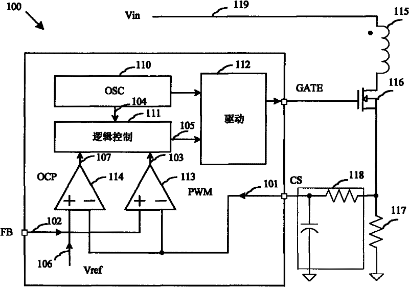
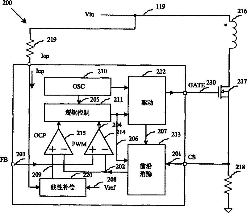
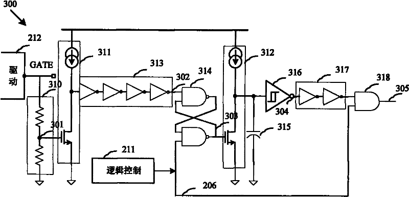
[0023] The invention provides an overcurrent protection system and method for a switch power converter. When the MOSFET switch is turned on, the parasitic capacitance is suddenly discharged, which will generate a large current spike in the loop. If the current value is detected at this time, false triggering will occur. In order to prevent the system from detecting the switch tube current prematurely, it is necessary to shield the interference of the spike pulse. Traditional switching power supplies often need to connect a larger RC filter to the current detection terminal to shield the spikes, which will increase the cost of the power supply system. The leading edge blanking circuit in the overcurrent protection system of the present invention enables the switch to be turned on for a period of time before detecting the current, eliminates the interference of spike pulses, prevents the occurrence of false trigger actions, and saves an external RC network for the system, Reduc...


PUM


Abstract

The invention discloses a system for providing over-current protection for a switching power converter. The system comprises a front-edge blanking circuit, a linear compensation circuit and an over-current protection comparer, wherein the front-edge blanking circuit is configured to generate a front-edge blanking effect on a detection signal of a current which flows through an external switching tube of the switching power converter; the linear compensation circuit is configured for performing linear compensation on a threshold voltage of the over-current protection comparer; and the over-current protection comparer is configured for generating an over-current protection comparison signal. By a linear compensation over-current protection circuit, the time delay of a system internal over-current protection output signal is taken into consideration, so the permanent damage of a switching tube of a metal-oxide semiconductor field effect transistor (MOSFET) caused by large-current conduction which may be generated at a high input voltage is avoided; and a maximum output power is stabilized, so the maximum power planarization of a power system can be realized in a full-voltage input range.

Description

technical field [0001] The invention relates to the field of switching power supplies, more specifically, the invention provides an overcurrent protection system for switching power supply converters. Background technique [0002] As the power supply equipment of all electronic products, the power supply is not only designed to meet the performance requirements, but also its own protection measures are also very important. Such as over-current protection, over-voltage protection, over-temperature protection and so on. At present, in switching power converters, high-power MOSFET switching tubes with high-frequency switching characteristics have been widely used. However, its ability to withstand short-term overload is weak. Under abnormal conditions such as faults or short circuits in the load circuit system, the power consumption will increase sharply, which will affect the normal operation of the MOSFET switch tube and may cause permanent damage to the power supply system....

Claims


Application Information

Patent Timeline
Patent Type & Authority Applications(China)
IPC IPC(8): H02M1/32
Inventor 叶英赵宏伟李拓
Owner 大连精拓光电有限公司
Why Eureka
Try Eureka