
Hydraulic actuator and hydraulic vibration test device

A vibration test and actuator technology, applied in fluid pressure actuation devices, vibration tests, fluid pressure actuation system components, etc., to achieve the effect of suppressing energy consumption

Active Publication Date: 2011-10-12
KOKUSAI KEISOKUKI KK
View PDF1 Cites 3 Cited by
  • Summary
  • Abstract
  • Description
  • Claims
  • Application Information

AI Technical Summary

Problems solved by technology

In addition, the rotation direction of the motor 112 is limited to one direction, that is, the motor 112 can only rotate forward

Method used


Image

  • Hydraulic actuator and hydraulic vibration test device
  • Hydraulic actuator and hydraulic vibration test device
  • Hydraulic actuator and hydraulic vibration test device

Examples


Embodiment

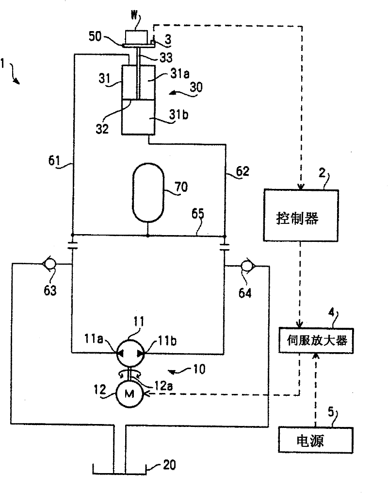
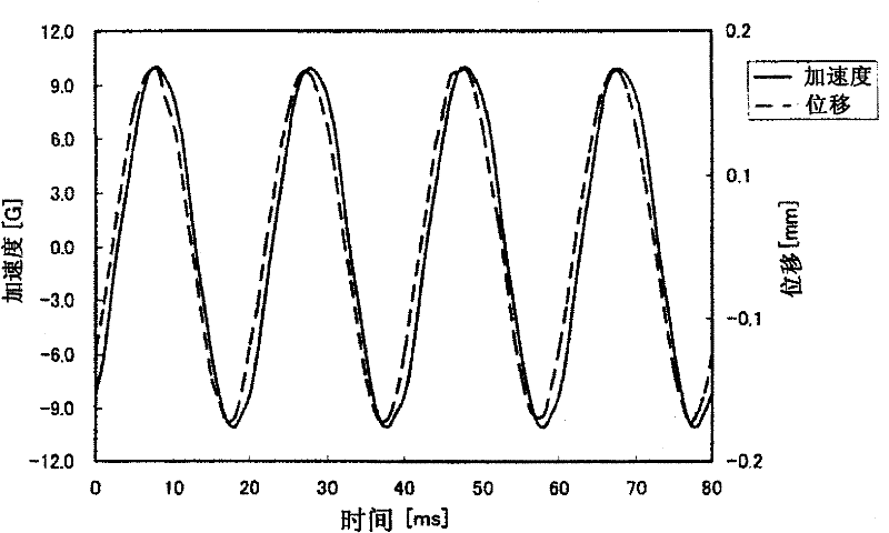
[0046] Next, the results of a vibration test performed using the vibration test device 1 of the present embodiment described above and the results of a vibration test performed using a vibration test device that does not include a pressure accumulator will be described. image 3 It is a graph of the acceleration and displacement of the vibrating table measured when the target waveform of a sine wave with a frequency of 50 Hz is supplied to the vibration test apparatus 1 (example) of this embodiment and the subject W is vibrated . also, Figure 4 It is a graph of acceleration and displacement of a vibrating table measured when a target waveform of a sine wave with a frequency of 50 Hz is supplied to a vibration test device (comparative example) not equipped with a pressure accumulator, and the subject W is vibrated ongoing. In addition, there is no structural difference between the vibration test device of the example and the vibration test device of the comparative example e...


PUM


Abstract

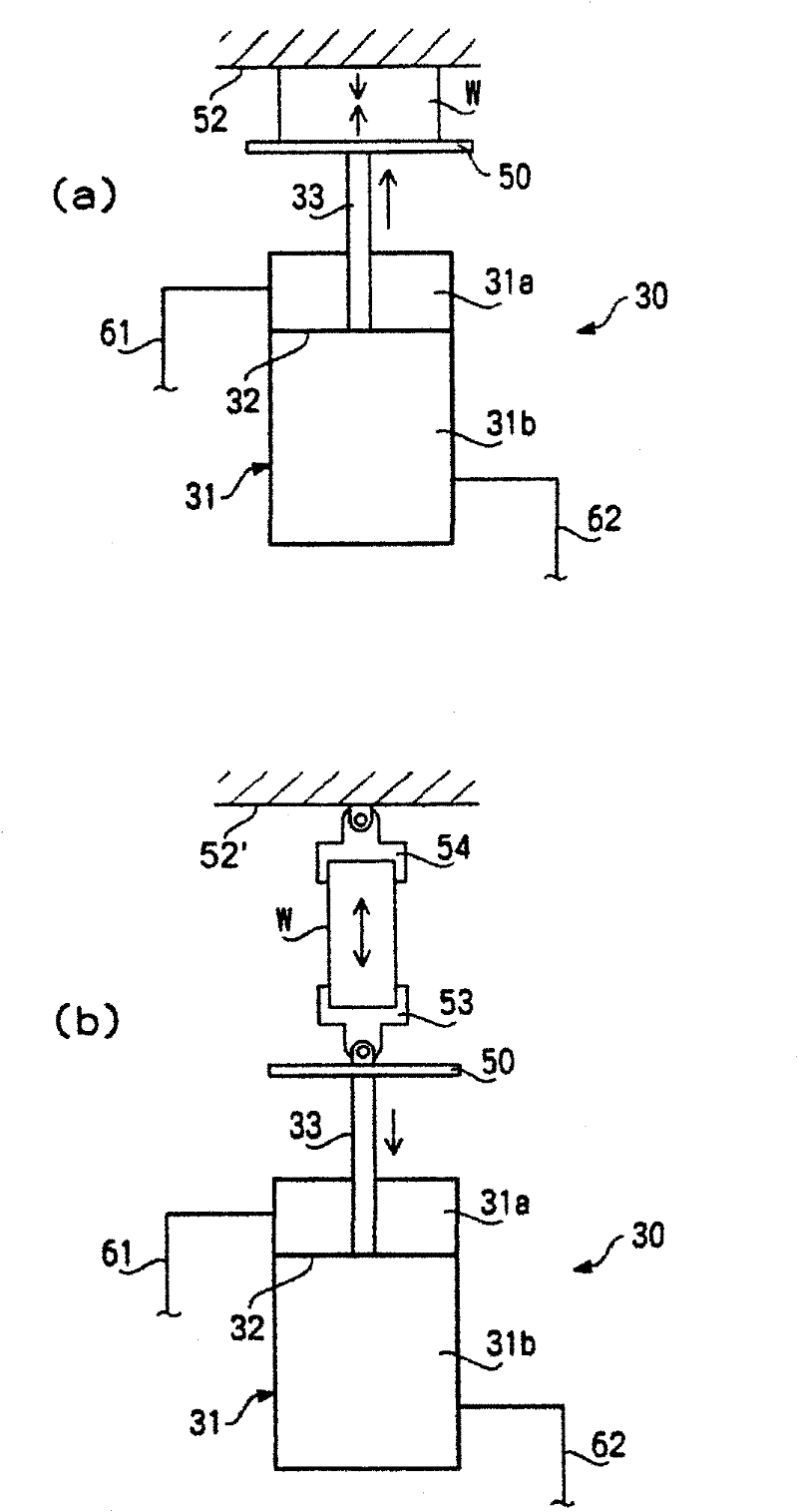
A hydraulic actuator provided with a hydraulic pump and a hydraulic cylinder unit. The hydraulic pump has a first suction and discharge opening and a second suction and discharge opening and can be reversely operated. The hydraulic cylinder unit is provided with a piston, a sleeve having an inner space partitioned by the piston into a first pressure chamber and a second pressure chamber, and a piston rod connected to the piston and having a front end projecting to the outside of the sleeve. The hydraulic actuator is provided with first piping for interconnecting the first pressure chamber and the first suction and discharge opening, and also with second piping for interconnecting the second pressure chamber and the second suction and discharge opening. When the hydraulic piston is reversely operated, hydraulic pressure is alternately applied to the first and second pressure chambers to vertically move the piston. The hydraulic actuator is further provided with a bypass pipe for interconnecting the first and second piping and also with an accumulator provided in the middle of the bypass pipe and applying back pressure to the first and second pressure chambers. A vibration test device equipped with the hydraulic actuator is also provided.

Description

technical field [0001] The invention relates to an oil pressure actuator capable of high-speed reverse driving and an oil pressure vibration test device. Background technique [0002] As a vibration test device that vibrates a test object with a hydraulic cylinder, for example, a device using a positive displacement pump and a servo valve as described in JP 2000-2617 is known. Such a vibration test device is capable of vibrating the subject at a high frequency while applying a large load to the subject. Figure 5 An example of a circuit diagram showing a hydraulic vibration tester using a servo valve. [0003] Figure 5 The shown hydraulic vibration test device 101 has a pump unit 110 , an actuating oil tank 120 , a hydraulic cylinder unit 130 , a servo valve 140 , and a vibration table 150 . The workpiece W is fixed on the vibration table 150 , and the vibration table 150 is reciprocated to apply vibration to the workpiece W. [0004] The pump unit 110 drives a positive d...

Claims


Application Information

Patent Timeline
IPC IPC(8): G01M7/02
CPCG01M7/022G01N3/36G01N2203/0008G01N2203/0048F15B11/02F15B15/14F15B21/02G01M7/02
Inventor 松本繁宫下博至村内一宏角田光央
Owner KOKUSAI KEISOKUKI KK
Learn More