Single-motor and wide-speed-regulation range crucible rod operation speed regulating system and speed regulation method

A technology of speed regulation system and wide speed regulation, which is applied in chemical instruments and methods, single crystal growth, self-solidification method, etc., and can solve problems such as narrow speed range, high processing and manufacturing costs, and discontinuity

Inactive Publication Date: 2011-10-19
XIAN XIGUANG MACHINERY MFG
View PDF6 Cites 1 Cited by
  • Summary
  • Abstract
  • Description
  • Claims
  • Application Information

AI Technical Summary

Problems solved by technology

In the prior art, a single stepping motor is often used to drive the movement of the crucible rod. This mechanism has a double-speed function, but the speed range is narrow, only slow speed 0.2mm / h~5.6mm / h, fast 0.2cm / min~4.7cm / h min speed range, and the stepper motor has the disadvantages of unstable, unsmooth, and discontinuous operation when it runs at low speed; while using dual motors to realize this function, the mechanical mechanism is complex and the manufacturing cost is high
[0003] Moreover, the period of crystal growth is relatively long. During the crystal growth process, no power failure is allowed. If there is a sudden power failure, the crystal growth will be interrupted, and the quality of the grown crystal will be seriously affected. Unexpected power failures such as heavy rains will cause the crucible rod to slide down automatically, and the entire crystal will be scrapped, which will not only cause a huge waste of energy, but also bring irreparable economic losses to the manufacturer.

Method used


Image

  • Single-motor and wide-speed-regulation range crucible rod operation speed regulating system and speed regulation method
  • Single-motor and wide-speed-regulation range crucible rod operation speed regulating system and speed regulation method
  • Single-motor and wide-speed-regulation range crucible rod operation speed regulating system and speed regulation method

Examples


Embodiment Construction

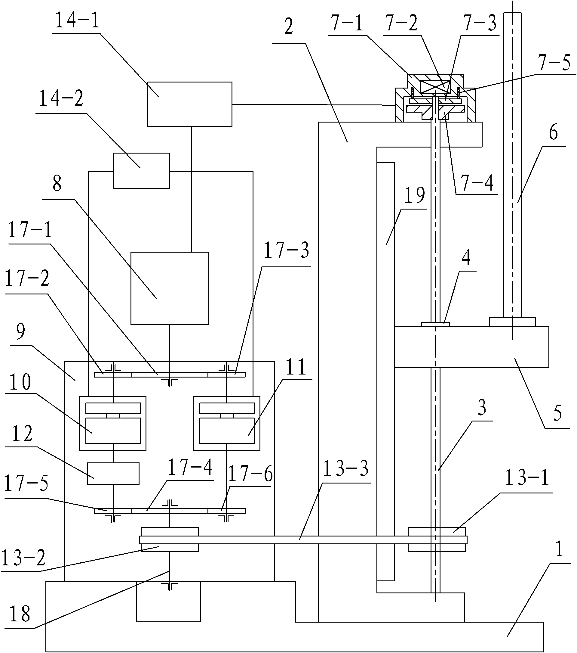
[0061] Such as figure 1 , figure 2 and image 3 As shown, the crucible rod operation speed regulation system with a wide speed regulation range of single motor according to the present invention includes a base 1, the top of the base 1 is provided with a crucible rod operating device, a power connected to the crucible rod operating device and The speed regulation system, and the operation and speed regulation control system connected with the crucible rod operating device and the power and speed regulation system;

[0062] The crucible rod running device includes a column 2 whose bottom end is connected to the base 1, a ball linear guide 19 fixedly connected to the side wall of the column 2, a ball screw 3 rotatably connected to the column 2 and parallel to the ball linear guide 19 , the ball screw nut 4 sleeved on the ball screw 3, the slider 5 that is connected with the ball screw nut 4 and the ball linear guide rail 19 and runs up and down on the ball screw rod 3 along t...


PUM


Abstract

The invention discloses a single-motor and wide-speed-regulation range crucible rod operation speed regulating system and a speed regulation method. The system comprises a base, a crucible rod operation device arranged on the top end of the base, a power and speed regulating system connected with the crucible rod operation device, and an operation and speed control system connected with the crucible rod operation device and the power and speed regulating system, wherein the power and speed regulating system comprises a direct-current speed measuring torque machine set and a speed regulating device which consists of two electromagnetic clutches, a harmonic wave reducer and a timing belt pulley 2. The method comprises the following step: calibrating a speedometer V before use; in a chargingstage, allowing the crucible rod to operate upward in an actually required quick operation speed direction; in a crystal normal growth section, allowing the crucible rod to operate downward in an actually required slow operation speed direction; and in a discharge stage, allowing the crucible rod to operate upward in the actually required quick operation speed direction. In the invention, the structure is simple, the design is reasonable, the speed regulation range is wide, the manufacturing cost is low, the use and operation are convenient and quick, and the promotion and use are convenient.

Description

technical field [0001] The invention belongs to the technical field of motion control, and relates to a speed regulation system and a speed regulation method for the operation of a crucible rod during the crystal growth process, in particular to a speed regulation system and a speed regulation method for the operation of a crucible rod with a wide speed regulation range of a single motor. Background technique [0002] The crucible descent method is a commonly used crystal growth method. The material used for crystal growth is packed in a cylindrical crucible, slowly descends, and passes through a heating furnace with a certain temperature gradient. The furnace temperature is controlled at slightly higher than Near the melting point of the material, the material in the crucible is melted when passing through the heating area. When the crucible continues to descend, the temperature at the bottom of the crucible first drops below the melting point and begins to crystallize. The ...

Claims


Application Information

Patent Timeline
IPC IPC(8): C30B11/00
Inventor 陆健王强胡辉
Owner XIAN XIGUANG MACHINERY MFG
Why Eureka
Try Eureka