Alternating-current pixel driving circuit and method for active organic light-emitting diode (OLED) display

A pixel drive circuit and light-emitting diode technology, applied in static indicators, instruments, etc., can solve the problems of unrealized OLED AC drive, achieve the effect of compensating threshold voltage drift and improving brightness uniformity

Inactive Publication Date: 2011-10-19
SOUTH CHINA UNIV OF TECH
View PDF4 Cites 117 Cited by
  • Summary
  • Abstract
  • Description
  • Claims
  • Application Information

AI Technical Summary

Problems solved by technology

The reverse bias of the OLED can reduce the charge accumulation of the organic layer in the OLED, help the OLED recover from degradation, improve the current-voltage characteristics of the OLED and increase the energy utilization efficiency, but it will not affect the quantum efficiency
[0004] At present, most of the AMOLED pixel circuit designs either implement AC driving of OLED to delay the degradation of OLED characteristics to improve its working life, but fail to compensate for TFT threshold voltage drift and OLED characteristic degradation; or realize compensation for TFT threshold voltage drift and OLED characteristics Degradation, but AC drive of OLED not realized

Method used


Image

  • Alternating-current pixel driving circuit and method for active organic light-emitting diode (OLED) display
  • Alternating-current pixel driving circuit and method for active organic light-emitting diode (OLED) display
  • Alternating-current pixel driving circuit and method for active organic light-emitting diode (OLED) display

Examples


Embodiment

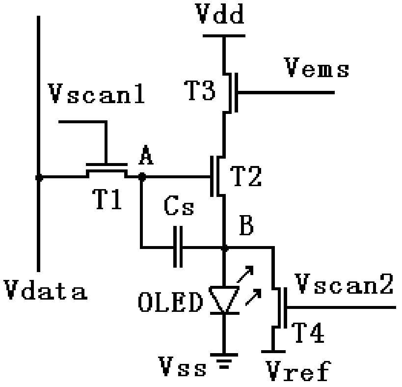
[0023] Such as figure 1 As shown, the AC pixel driving circuit diagram of the active organic light emitting diode display of the present invention includes a first transistor T1, a second transistor T2, a third transistor T3, a fourth transistor T4, a storage capacitor Cs, a first scanning control line Vscan1, an AC Drive control line Vscan2, light emission control line Vems, power line Vdd, ground line Vss, reference potential line Vref, data line Vdata, organic light emitting diode OLED (hereinafter only represented by OLED). The aforementioned transistors may be any one of polysilicon thin film transistors, amorphous silicon thin film transistors, zinc oxide-based thin film transistors or organic thin film transistors.

[0024] The drain of the first transistor T1 is connected to the data line Vdata, the gate is connected to the first scanning control line Vscan1, and the source is connected to the A terminal of the storage capacitor Cs, and the first transistor T1 is used ...


PUM


Abstract

The invention discloses an alternating-current pixel driving circuit and method for an active organic light-emitting diode (OLED) display. The driving circuit comprises a driving transistor, a switch transistor, a storage capacitor and an OLED, wherein the drain of the first transistor is connected with a data wire; the grid of the first transistor is connected with a first scanning control wire; the source of the first transistor is connected with the end A of the storage capacitor; the drain of a second transistor is connected with the source of a third transistor; the grid of the second transistor is connected with the end A of the storage capacitor and the source of the first transistor; the source of the second transistor is connected with the drain of a four transistor and the end B of the storage capacitor, and is connected with the ground through the OLED; the drain of the third transistor is connected with a power wire; the grid of the third transistor is connected with a light-emitting control wire; the grid of the fourth transistor is connected with a second scanning control wire; and the source of the fourth transistor is connected with a reference potential. According to the driving circuit and method, the OLED works in an alternating-current driving mode, so that the characteristics of the OLED are recovered from degeneration state, the service life of the OLED is prolonged effectively, the threshold voltage drift of a thin film transistor and the degeneration of OLED cut-in voltage can be compensated effectively, and the uniformity of a display picture is enhanced.

Description

technical field [0001] The invention relates to a pixel driving technology of a light emitting diode display, in particular to an AC pixel driving circuit and a driving method of an active organic light emitting diode display. Background technique [0002] Active-Matrix Organic Light Emitting Diode (AMOLED) displays have attracted wide attention due to their advantages of small size, simple structure, self-illumination, high brightness, wide viewing angle, and short response time. [0003] At present, the thin film transistors used in AMOLED display mainly include amorphous silicon thin film transistors (a-Si:H TFT) and polysilicon thin film transistors (Poly-Si TFT). However, due to the metastability of amorphous silicon materials, the threshold voltage of a-Si:H TFTs suffers severe drift over time due to electrical stress. Due to the random distribution of grain boundaries on the polysilicon material, the threshold voltage of Poly-Si TFTs is unevenly distributed among pix...

Claims


Application Information

Patent Timeline
Patent Type & Authority Applications(China)
IPC IPC(8): G09G3/32G09G3/3233
Inventor 吴为敬彭俊彪周雷张立荣王磊许伟
Owner SOUTH CHINA UNIV OF TECH
Why Eureka
Try Eureka