Continuous settling tank

A settling tank, continuous technology, applied in the direction of settling tanks, liquid separation, chemical instruments and methods, etc., can solve the problems of reducing the cross-sectional area of ​​the actual flow channel, increasing the velocity gradient of the flow system, multiple settlement areas, etc., to achieve faster relative The effect of speed of movement, utilization of internal space, and large settlement area

Inactive Publication Date: 2011-10-26
TIANJIN UNIV +1
View PDF5 Cites 6 Cited by
  • Summary
  • Abstract
  • Description
  • Claims
  • Application Information

AI Technical Summary

Problems solved by technology

Moreover, multiple structures such as perforated plates 21, baffles 24, and baffles 25 are installed in the settling tank to interfere with and change the flow direction in order to promote the separation of phases, which not only leads to complex structures, but also significantly reduces the actual flow path The cross-sectional area increases the internal velocity gradient of the flow system, and makes the settling tank unable to provide the proper settling area, which damages the effect of gravity settling and even causes some operational difficulties.
[0004] In the existing technology, the continuous settling tank used in the phase separation process of the partial hydrogenation reaction product of single-ring aromatic hydrocarbons frequently changes the flow direction, causing too much interference to the flow, and the annular overflow area and the central reducing pipe occupy too much settling area , and the radial distance from the liquid outlet of the central reducer to the annular overflow weir is too short, these factors are not conducive to the separation of light and heavy phases
In addition, the arrangement of the components in the conical part is not conducive to the stability of the phase separation process, which makes it difficult to measure and control the interface between light and heavy liquid layers, resulting in additional loss of catalyst

Method used


Image

  • Continuous settling tank
  • Continuous settling tank
  • Continuous settling tank

Examples


Embodiment Construction

[0025] The present invention will be described in detail below in conjunction with the accompanying drawings and embodiments.

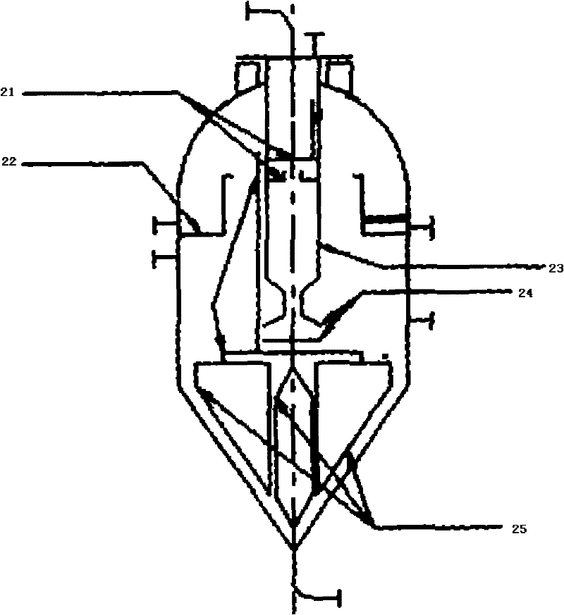
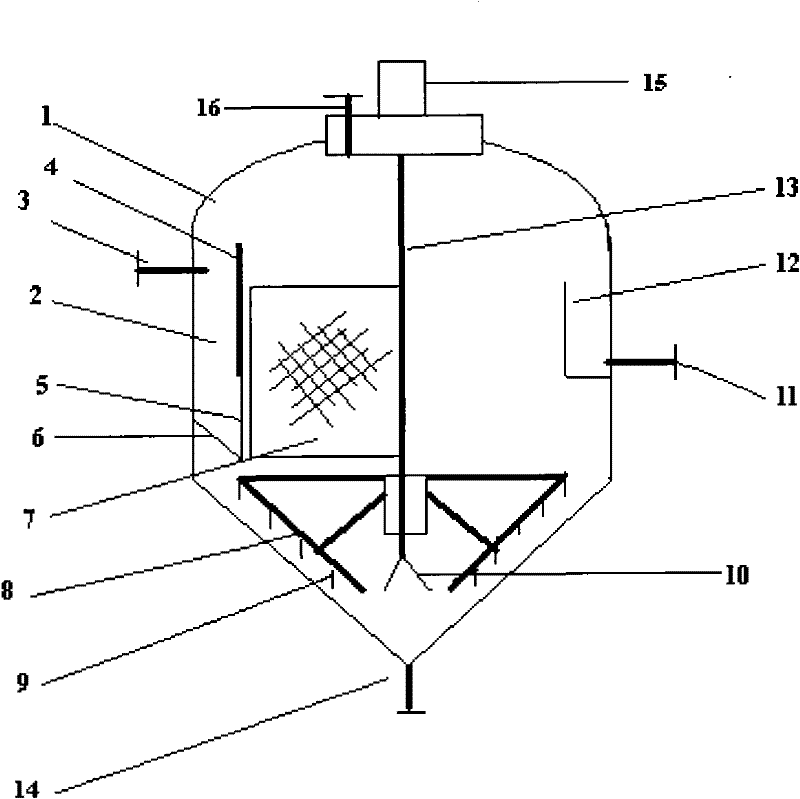
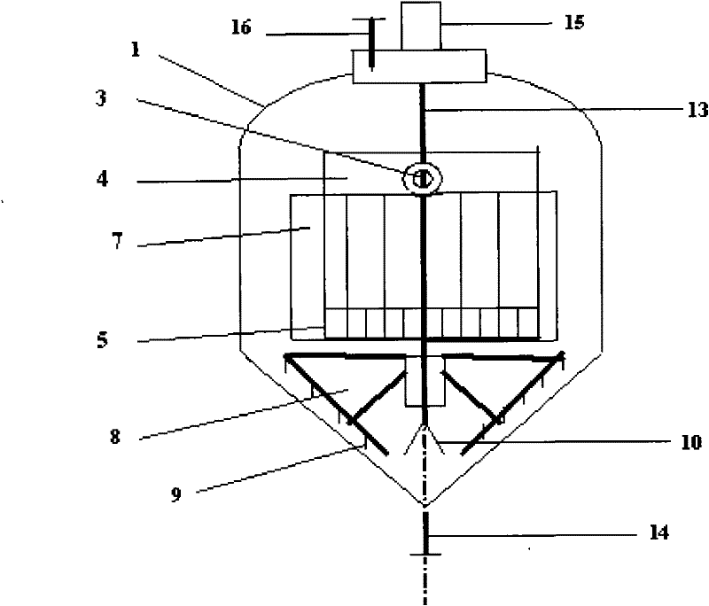
[0026] Such as figure 2 As shown, the settling tank includes a shell 1, the upper part of the shell 1 is a circular cylinder, and the lower part is a conical cylinder. Such as figure 2 , 3 As shown in and 4, a bow-shaped feed trough 2 is set in the circular cylinder of the housing 1, and a feed inlet 3 is set on the shell side wall of the bow-shaped feed trough 2. The bow-shaped feeding trough 2 is composed of the inner wall of the circular cylinder of the shell 1, the straight wall plate 4, the grid distribution plate 5 and the bottom plate 6, forming a bow-shaped top view, see Figure 5 . The chord length of the bow-shaped feed trough 2, that is, the ratio of the width L of the straight wall plate 4 to the diameter D of the circular cylinder is 0.35 to 0.75, which minimizes the area occupied by the feed trough while minimizing the mixing at th...


PUM

PropertyMeasurementUnit
angleaaaaaaaaaa

Abstract

The invention discloses a continuous settling tank which comprises a shell, wherein the shell is provided with a circular cylinder at the upper part and a conical cylinder at the lower part; an overflow weir is arranged in the circular cylinder; an underflow outlet is arranged at the bottom of the conical cylinder; an arch-shaped feeding slot is arranged in the circular cylinder of the shell; the arch-shaped feeding slot comprises the inner side wall of the circular cylinder, a flat wall plate, a grid distributing plate and a baseboard; the grid distributing plate is arranged under the flat wall plate; upper and lower ends of the grid distributing plate are respectively fixedly connected to the flat wall plate and the baseboard; a plurality of porous guiding vanes are symmetrically and obliquely arranged outside the flat wall plate; gaps are reserved between the guiding vanes and the flat wall plate; and a rotary rake is arranged on the conical cylinder at the lower part of the shell. By using the continuous settling tank provided by the invention, the maximum settling area is supplied as much as possible, an interior space of equipment is efficiently utilized, a settling separating effect is improved, and the loss of solid materials such as catalyst can be reduced.

Description

technical field [0001] The invention relates to a settling equipment in the field of chemical industry, in particular to a continuous settling tank. Background technique [0002] The effluent of the reaction equipment for preparing cyclohexene by partial hydrogenation of benzene under the action of a solid catalyst is a three-state four-phase reaction system: gas phase (gaseous hydrogen), oil phase (liquid benzene, cyclohexene, etc.), Aqueous phase (liquid water) and solid phase (fine particles of solid catalyst suspended in the aqueous phase). [0003] The gravity continuous settling tank used in the prior art in the phase separation process of the partial hydrogenation reaction product of monocyclic aromatic hydrocarbons, such as figure 1 As shown, the upper part is a circular cylinder and the lower part is a conical cylinder. The feed enters from the center of the top and flows down through the central reducing tube 23 until it reaches near the height of the joint betwee...

Claims


Application Information

Patent Timeline
Patent Type & Authority Applications(China)
IPC IPC(8): B01D19/00B01D17/025B01D21/06
Inventor 汪宝和董广昌魏东炜田红兵殷金柱朱璟
Owner TIANJIN UNIV
Why Eureka
Try Eureka