Controllable test vector generator based on linear feedback shift register

A linear feedback shift and test vector technology, applied in static memory, instruments, etc., can solve the problems of high test power consumption, high hardware overhead, increased test time and power consumption, etc., and achieve low test cost and low hardware overhead. Effect

Inactive Publication Date: 2014-03-26
UNIV OF ELECTRONICS SCI & TECH OF CHINA
View PDF6 Cites 0 Cited by
  • Summary
  • Abstract
  • Description
  • Claims
  • Application Information

AI Technical Summary

Problems solved by technology

However, its original test vector sequence must contain test vectors that do not contribute to faults, and the newly added test vectors will increase the length of the entire test vector sequence, resulting in increased test time and power consumption, and the test vector generator Implementation is more complicated
[0012] From the above technical solutions, we can see that the generation method of test vectors in the prior art has not been well solved for the problems of large hardware overhead, long test application time, large test power consumption, and low fault coverage. solve

Method used


Image

  • Controllable test vector generator based on linear feedback shift register
  • Controllable test vector generator based on linear feedback shift register
  • Controllable test vector generator based on linear feedback shift register

Examples


Embodiment

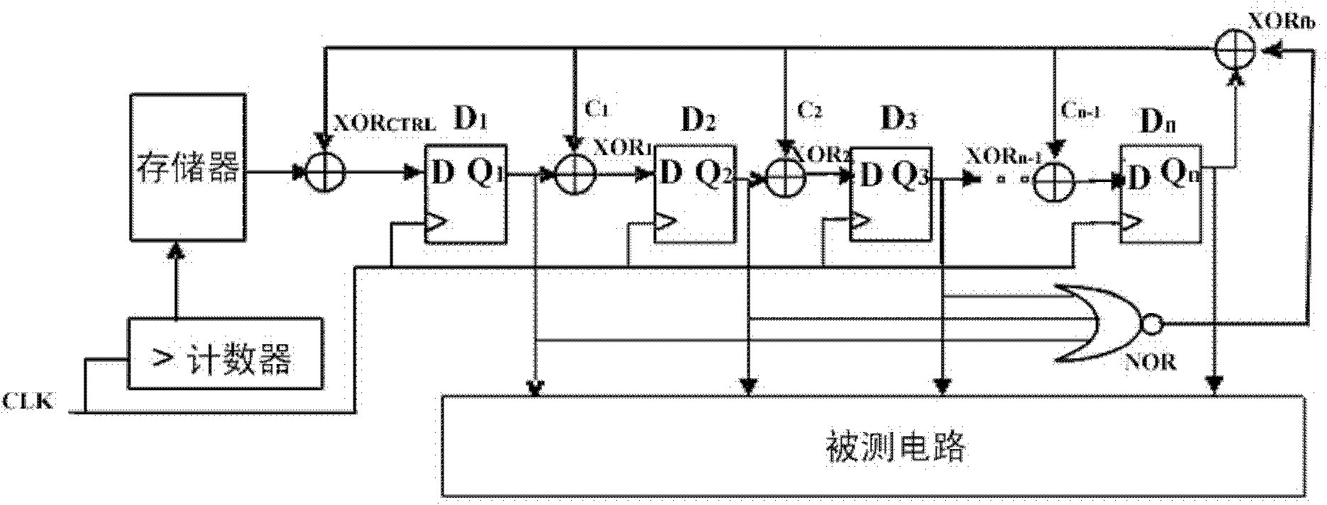
[0029] figure 1 It is a principle diagram of a specific implementation of the controllable test vector generator based on the linear feedback shift register of the present invention.

[0030] In this example, if figure 1 Shown, the present invention is based on the controllable test vector generator of linear feedback shift register, comprises:

[0031] One consists of n serially connected D flip-flops D 1~n XOR with n-1 XOR gates 1~n-1 The inner connection type linear feedback shift register formed;

[0032] An n-1-bit input NOR gate NOR and an exclusive OR gate XOR fb The feedback network formed, the n-1 input terminals of the NOR gate NOR are respectively connected to the D flip-flop D 1~n-1 The output Q 1~n-1 , XOR gate XOR fb The two input ends of the NOR gate are respectively connected to the output end of the NOR gate and the D flip-flop D n Output Q n;Exclusive OR gate XOR in the feedback network fb The output terminals of are respectively connected to n-1 ex...

example

[0077] In this example, the C17 circuit is taken as an example to illustrate the test vector generator of the present invention.

[0078] The main circuit of C17 is composed of 6 NAND gates with 5 input terminals. If the sequential test vector sequence of the maximum period is generated by the ergodic linear feedback shift register for testing, the ergodic linear feedback composed of 5 D flip-flops The shift register can achieve a fault coverage rate of 99.3%, with all "0" bits as the initial state, and its test vector set is shown in Table 1.

[0079]

[0080] Table 1

[0081] 00000

11001

11000

01001

01100

00001

00110

10001

00011

10000

[0082] Table 2

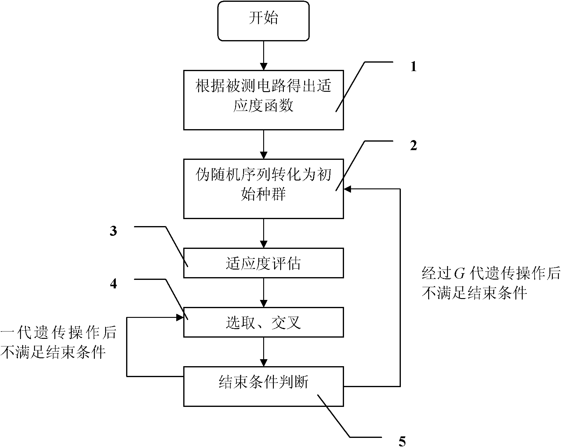
[0083] Under the same fault coverage requirement, the test vector generator of the present invention is used. First, according to the fault characteristics of the C17 reference circuit, the fitness function used by the genetic algorithm ...


PUM


Abstract

The invention discloses a controllable test vector generator based on a linear feedback shift register (LFSR). The controllable test vector generator comprises three sections: 1, a control code sequence generation section comprising a counter and a memory; 2, a sequence pseudo random test vector sequence generation section comprising a inscribe LFSR; 3, a feedback network section formed by n-1 bit input or a non-gate NOR and an exclusive-OR gate XORfb. Depending on the test vectors required to be generated, the control code sequence is acquired, wherein the control code sequence is stored in the memory and is provided for controlling a run of the inscribe LFSR, such that the sequence or jump output pseudo random sequence of the inscribe LFSR is adopted as the test vector. With the present invention, only the control code memory, the counter, the feedback network section formed by the n-1 bit input or the non-gate NOR and the exclusive-OR gate XORfb, and a control exclusive-OR gate XORCTRL are added on the base of the inscribe LFSR, such that hardware expense is few, and test cost is low.

Description

technical field [0001] The invention belongs to the technical field of design for testability of large-scale integrated circuits, and more specifically relates to a controllable test vector generator based on a linear feedback shift register for built-in self-test. Background technique [0002] With the sharp increase in the number of gates in IC design, the test vector size of a large IC is also growing rapidly. At the same time, due to the continuous increase of the clock frequency of the circuit system, it is often difficult to test the integrated circuit after it is produced. It often requires the use of very expensive test instruments and a long test time, and it is difficult to perform a comprehensive test. A better way to solve this problem is to use design for testability technology, that is, to consider its test problems while designing integrated circuits, so that integrated circuits can be tested more easily after they are produced. Built-in self-test (Built-In-S...

Claims


Application Information

Patent Timeline
Patent Type & Authority Patents(China)
IPC IPC(8): G11C29/56
Inventor 龙兵杨会平田书林刘震
Owner UNIV OF ELECTRONICS SCI & TECH OF CHINA
Why Eureka
Try Eureka