
Multi-cycle arrangement carrier-free double-integrated chip (IC) package and production method
A technology of chip package and production method, which is applied in semiconductor devices, electric solid state devices, semiconductor/solid state device manufacturing, etc., to achieve the effects of improving test yield and reliability, good electrical performance, and low distortion
- Summary
- Abstract
- Description
- Claims
- Application Information
AI Technical Summary
Problems solved by technology
Method used
Image

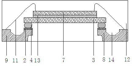
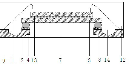
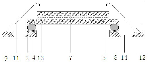
Examples
Embodiment 1
[0054] Using 8-inch to 12-inch thinning machine, adopts rough grinding, fine grinding and polishing anti-warping process, the wafer with bump chip is thinned to 250μm, rough grinding speed: 6μm / s, fine grinding speed: 1.0μm / s; the thickness of the wafer without bumps is 100μm, the rough grinding speed is 4μm / s, the fine grinding speed is 0.8μm / s, and the chip warpage prevention process is adopted;
[0055] (2), scribing
[0056] ≤8-inch wafers use DISC 3350 double-knife dicing machine, 8-inch to 12-inch wafers use A-WD-300TXB dicing machine, and the scribing speed is controlled at ≤10mm / s;
[0057] (3), on the core
[0058] For one-time chipping, IC chips with no carrier frame and bumps are used, and flip-chip chipping is adopted; for the semi-finished products of flip-chip chipping, IC chips 7 without bumps are used for secondary chipping, using AD828 / 829 For the core machine, apply glue 13QMI538 on the back of the IC chip 3 with bumps on the first layer, and then stick th...
Embodiment 2
[0081] Use 8-inch to 12-inch thinning machine, adopt rough grinding, fine grinding and polishing anti-warping process, the wafer with bump chip is thinned to 200μm, rough grinding speed: 3μm / s, fine grinding speed: 0.6μm / s; the thickness of the wafer without bumps is 100 μm, the rough grinding speed is 2 μm / s, the fine grinding speed is 0.4 μm / s, and the chip warpage prevention process is adopted;
[0082] (2), scribing
[0083] With embodiment 1;
[0084] (3), on the core
[0085] With embodiment 1;
[0086] (4), Underfill & Curing
[0087] For the semi-finished product of the secondary flip-chip, select an insulating material with a low thermal expansion coefficient α1<1, heat the underfill to 80°C, use vacuum technology to underfill the bumps and frame pads, and finally in a QFN general-purpose oven Bake the product after filling 10 for about 30 minutes;
[0088] (5), pressure welding
[0089] With embodiment 1;
[0090] (6), plastic packaging
[0091] With embodim...
Embodiment 3
[0106] Use 8-inch to 12-inch thinning machine, adopt rough grinding, fine grinding and polishing anti-warping process, the wafer with bump chip is thinned to 200μm, rough grinding speed: 3μm / s, fine grinding speed: 0.6μm / s; the thickness of the wafer without bumps is 100 μm, the rough grinding speed is 2 μm / s, the fine grinding speed is 0.4 μm / s, and the chip warpage prevention process is adopted;
[0107] (2), scribing
[0108] With embodiment 1;
[0109] (3), on the core
[0110] The first core is made of a non-carrier frame and an IC chip 3 with bumps, and the core is flipped; the second core is carried out on the back of the IC chip 3 with bumps, and the IC chip 7 without bumps and glue are used. Diaphragm 6, the back side of the IC chip 7 without bumps has been pasted with adhesive film 6 before dicing. Using a core loading machine with adhesive film bonding function, first set the substrate heating temperature according to the type of adhesive film used. Fix the IC ...
PUM
 Abstract
Description
Claims
Application Information