Drive circuit for preventing oscillation of grid drive signals

A gate drive and drive circuit technology, applied in electrical components, output power conversion devices, etc., can solve the problems affecting the EMC characteristics of switching power supplies, product structure and human factors, and the improvement effect is not obvious, and achieve normal protection. Work, prevent shoot-through, reduce the effect of voltage change rate

Inactive Publication Date: 2011-11-02
SHUNDE POLYTECHNIC
View PDF3 Cites 16 Cited by
  • Summary
  • Abstract
  • Description
  • Claims
  • Application Information

AI Technical Summary

Problems solved by technology

However, the improvement effect of the above methods is not very obvious, and it is more affected by product structure and human factors.
Second, because the drive current provided by the control signal to the MOS tube rises rapidly (rising edge), it will cause a high turn-on surge, resulting in impact damage to the MOS tube, which will affect the EMC characteristics of the entire switching power supply to a certain extent

Method used


Image

  • Drive circuit for preventing oscillation of grid drive signals
  • Drive circuit for preventing oscillation of grid drive signals

Examples


Embodiment Construction

[0017] The present invention will be further described in detail with reference to the accompanying drawings and embodiments.

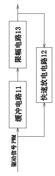
[0018] Such as figure 1 As shown, it is a driving circuit for preventing gate driving signal from oscillating. The feature of the present invention is to include a buffer circuit 11, a limiter circuit 13 and a fast discharge circuit 12, wherein the buffer circuit 11 receives the driving signal PWM and processes it to The signal is output to the limiter circuit 13, and the limiter circuit 13 processes the received signal and then outputs it to the gate of the MOS transistor Q2 and the fast discharge circuit 12, and the fast discharge circuit 12 also receives the drive signal PWM.

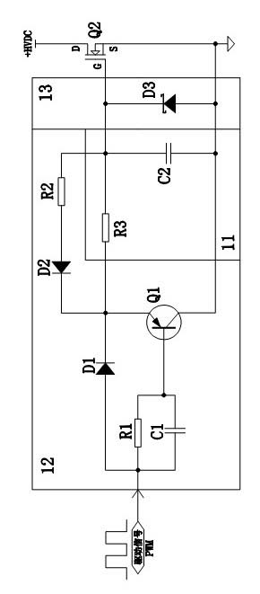
[0019] In this embodiment, the limiter circuit 13 includes a Zener diode D3, the anode of the Zener diode D3 is grounded, and the cathode is connected to the gate of the MOS transistor Q2.

[0020] The buffer circuit 11 includes a gate drive resistor R3 and a second capacit...


PUM


Abstract

The invention relates to a drive circuit for preventing the oscillation of grid drive signals. The drive circuit is characterized by comprising a buffer circuit, an amplitude limiting circuit and a rapid discharge circuit, wherein the buffer circuit receives and processes a drive signal PWM (Pulse Width Modulation) and then outputs the signal to the amplitude limiting circuit; the amplitude limiting circuit processes the received signal and then respectively outputs the signal to the grid of an MOS (Metal Oxide Semiconductor) transistor and the rapid discharge circuit; and the rapid discharge circuit also receives the drive signal PWM. The drive circuit has the advantages of lowering the voltage change rate of the MOS transistor, decreasing the open surge in the opening process, reducing the impact and damage to the MOS transistor, improving the EMC (Electro Magnetic Compatibility) property of the whole switch power supply, decreasing the turnoff loss, effectively avoiding the abnormal oscillation of drive signals, protecting normal working states of the MOS transistor and the circuit, and the like.

Description

technical field [0001] The invention relates to a drive circuit for preventing grid drive signal oscillation, belonging to the technical field of switching power supply drive, in particular to a drive circuit for preventing grid drive signal oscillation. Background technique [0002] At present, most switching power supply circuits use power devices, and power MOS tubes have been widely used in small and medium power power supply products due to their advantages of fast switching speed, low driving power and low power consumption. Two situations often occur in a circuit using a bridge topology. First, during the conversion process of two power devices on the same bridge arm, the gate drive signal will oscillate, and the loss of the power device is large at this time. When the oscillation amplitude is high, the power MOS tube that should be turned off will be turned on, thus causing the two power MOS tubes on the same bridge arm to be directly connected to form a short circui...

Claims


Application Information

Patent Timeline
Patent Type & Authority Applications(China)
IPC IPC(8): H02M1/08H02M1/32H02M1/44
Inventor 谢飞桂芳周秀君邓榆林昂勤树
Owner SHUNDE POLYTECHNIC
Why Eureka
Try Eureka