Three-force composite power device for moped

A technology of compound power and moped, which is applied in the direction of wheel transmission, circuit device, elastic motor, etc., and can solve the problems of difficulty in disassembling and installing batteries going up and down stairs, poor use effect and high cost of use

Inactive Publication Date: 2011-11-09
江苏磁源动力科技有限公司
View PDF7 Cites 10 Cited by
  • Summary
  • Abstract
  • Description
  • Claims
  • Application Information

AI Technical Summary

Problems solved by technology

However, the batteries of electric bicycles are easy to age, and the service life is not long, generally no more than one and a half years, and the effect becomes worse as they are used later
With the development of urban-rural integration, rural laborers have come to work in neighboring towns. Due to the long distance, usually about 30 kilometers, the existing electric bicycles cannot meet the travel requirements for a long time. Once the battery power is exhausted , the electric car becomes a trolley, and people are in a dilemma
Electric vehicles must be charged with mains electricity every day, otherwise they will not be able to walk. It is extremely inconvenient for people living in high-rise buildings to charge electricity every day. The batteries are large and heavy. It must be replaced regularly, otherwise the capacity will be greatly reduced and the mileage will be shortened
Therefore, the existing electric vehicles are not only troublesome to charge, but also cost a lot to use, and also pollute the environment.
During the driving process of electric vehicles, due to the uneven road surface, people will inevitably bump up and down irregularly when sitting on the seat. During the up and down bumping process, a large amount of gravitational potential energy is stored. Since there is no corresponding recycling device, these gravity Potential energy is wasted in vain and not recycled, which is a pity

Method used


Image

  • Three-force composite power device for moped
  • Three-force composite power device for moped
  • Three-force composite power device for moped

Examples


Embodiment Construction

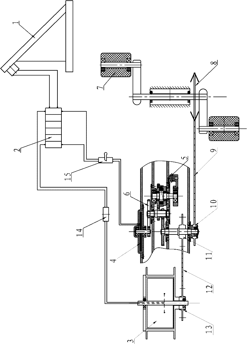
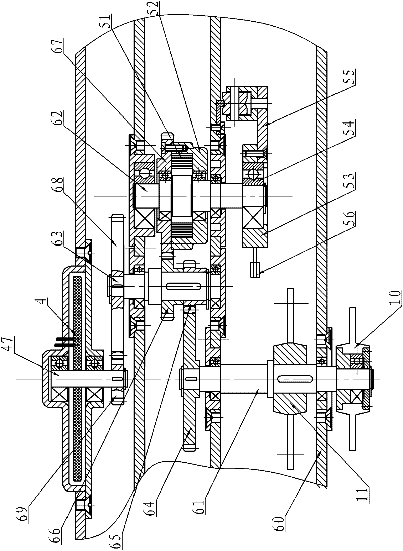
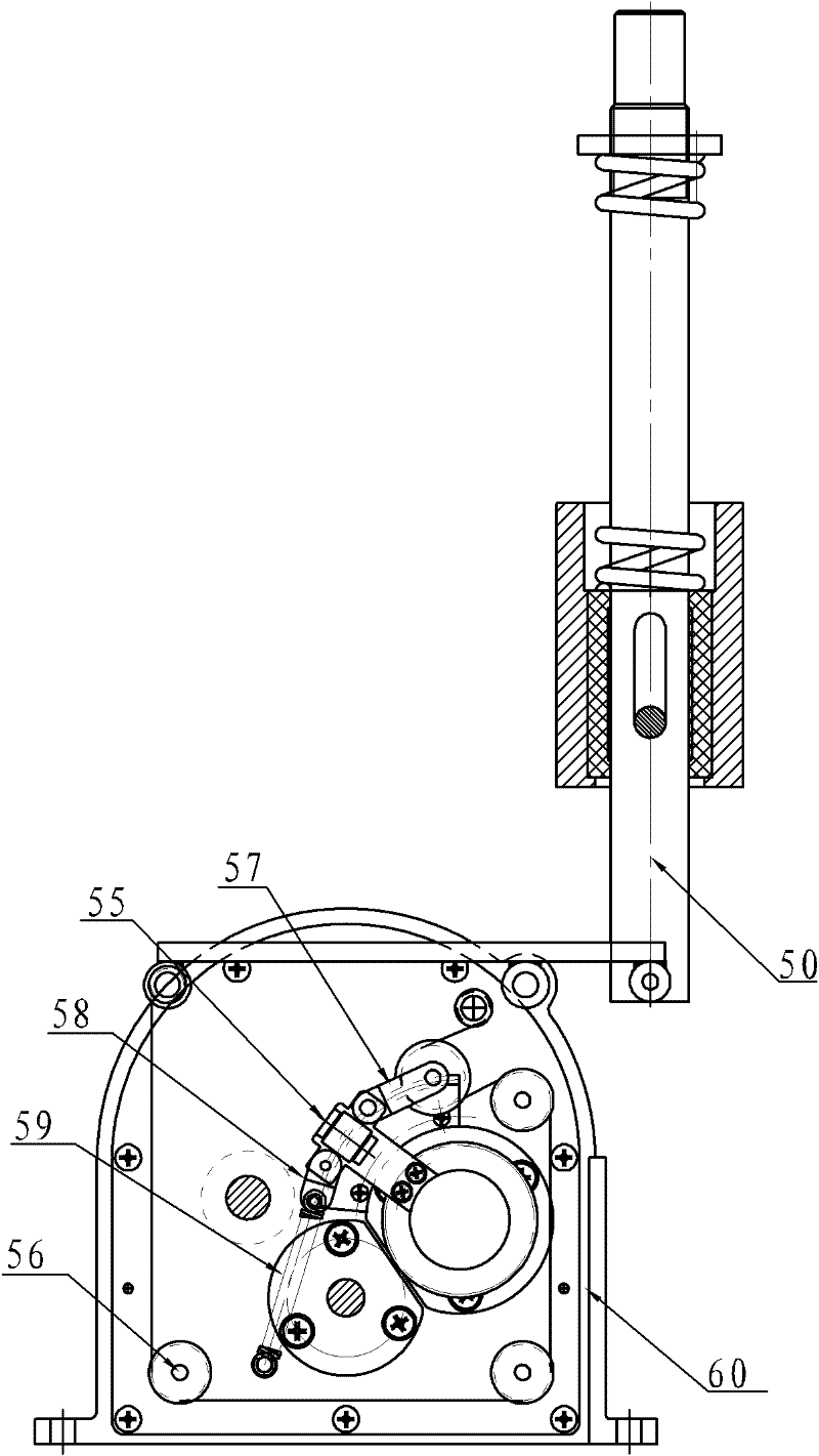
[0025] Attached below Figure 1~3 The specific embodiment of the present invention is described in detail:

[0026] A three-force compound power device for a moped, including a solar cell assembly 1, a lithium battery 2, a walking generator 3, a planar motor 4, an elastic energy storage device 5, a speed change mechanism 6, a pedal 7, a driving sprocket 8, and a primary chain 9. Transition one-way sprocket 10, transition sprocket 11, secondary chain 12, driving one-way sprocket 13, one-way charger 14 and current controller 15, solar battery module 1 is electrically connected with lithium battery 2, and power generation is performed by walking Machine 3 is electrically connected with lithium battery 2 through one-way charger 14, and lithium battery 2 is electrically connected with planar motor 4 through current controller 15, and walking generator 3 is installed on the rear wheel or front wheel drive of bicycle, and speed change mechanism 6 includes speed change Case 60, trans...


PUM


Abstract

The invention relates to a three-force composite power device for a moped. The device comprises a solar battery component, a lithium battery, a traveling generator, a planar motor, an elastic force energy storage device, a speed change mechanism, a pedal, a driving chain wheel, a primary chain, a transition one-way chain wheel, a filtering chain wheel, a secondary chain, a driving one-way chain wheel, a one-way charger and a current controller, wherein the solar battery component is a continuous energy input source; the traveling generator is a charging source for recycling excess kinetic energy; the lithium battery is an electric energy storage device; the planar motor is main power for driving the moped to run; the elastic force energy storage device converts the gravitational potential energy of a human body who bumps up and down in the running process into elastic force for driving the moped to run; the pedal provides initial kinetic energy for the moped; therefore, human force, the elastic force and electromagnetic force are compounded, the excess kinetic energy and the gravitational potential energy of the moped in the running process are recycled, the moped is hardly charged by a mains supply in the using process, and the device is a compounded energy-saving power device.

Description

Technical field: [0001] The invention relates to a power-assisted vehicle, in particular to a power device of the power-assisted vehicle. Background technique: [0002] At present, the commonly used mopeds are electric power-assisted bicycles, referred to as electric bicycles, which can travel 5 to 10 kilometers on a single charge. Electric bicycles can walk quickly without people pedaling, and charging is more convenient. In recent years, electric bicycles have gained rapid With the development, it has become the preferred means of transportation for people in small and medium-sized cities and towns for short-distance travel, and has been recognized by the public. However, the batteries of electric bicycles are prone to aging, and the service life is not long, generally no more than one and a half years, and the effect is worse in the later period. With the development of urban-rural integration, rural laborers have come to work in neighboring towns. Due to the long distan...

Claims


Application Information

Patent Timeline
Patent Type & Authority Applications(China)
IPC IPC(8): B62M6/40B62M11/04H02J7/14H02J7/00H02J15/00F03G7/08F03G1/00
CPCY02T10/7011Y02E70/30F03G7/08Y02E60/16
Inventor 陈国芳尹勇
Owner 江苏磁源动力科技有限公司
Why Eureka
Try Eureka