
Vertical heat accumulating type reduction furnace

A reduction furnace, regenerative technology, applied in the field of regenerative vertical reduction furnace, can solve the problems of vacuum atmosphere damage in the tank, difficulty in closing the lower tank mouth, thermal deformation of the lower tank mouth, etc., to achieve short construction period and energy saving The effect of remarkable effect and short recovery period

Inactive Publication Date: 2011-11-09
于思静 +1
View PDF6 Cites 2 Cited by
  • Summary
  • Abstract
  • Description
  • Claims
  • Application Information

AI Technical Summary

Problems solved by technology

The second is that it is difficult to close the lower tank mouth or the original pellets are wasted
If the lower tank mouth is closer to the furnace body, the high temperature of the tank body and the original pellets will be transferred to the lower tank mouth, causing the lower tank mouth to be heated and deformed, and the vacuum atmosphere in the tank will be destroyed
Since magnesium is crystallized in a vacuum atmosphere, if the vacuum cannot be maintained, crystalline magnesium will be oxidized at a furnace temperature of 1200°C; in order to avoid the occurrence of one situation, the tank mouth can be designed to be far away from the furnace body, but the furnace body and The original pellets between the bottom of the tank will not participate in the reaction due to insufficient heat, so this part of the material is wasted

Method used


Image

  • Vertical heat accumulating type reduction furnace
  • Vertical heat accumulating type reduction furnace

Examples


Embodiment Construction

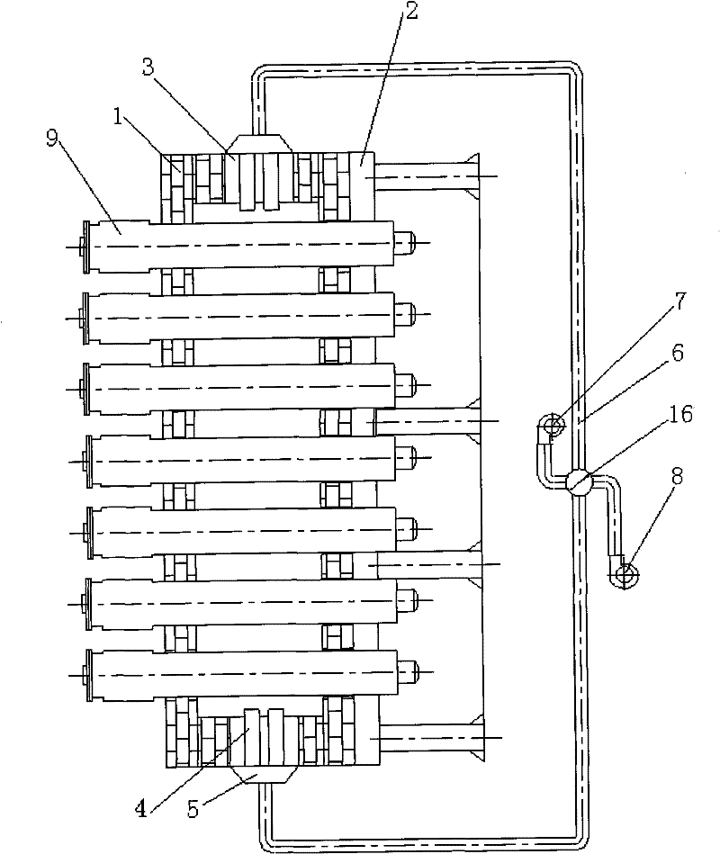
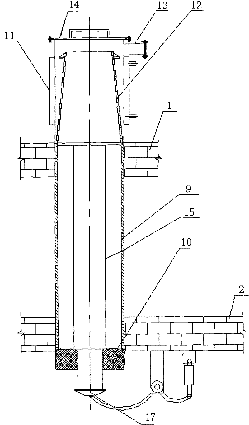
[0019] A regenerative vertical reduction furnace, the structure of which comprises:

[0020] Reduction furnace body 1 - the furnace body is a cavity-type cylindrical shell made of refractory materials, and the bottom of the furnace body is supported and fixed by a desktop support frame 2; the vertical side wall of the furnace body is equipped with a regenerative heating Cavity 3;

[0021] Regenerative heating device - the heating device includes a device shell that is adapted to the regenerative heating chamber on the vertical side wall of the reduction furnace body, and the fuel and combustion gas nozzles 4 and 5 are arranged in the shell;

[0022] Fuel and combustion-supporting gas inlet device - the device structure includes a delivery pipe 6 connected to the rear of the regenerative heating device shell, an induced draft fan 7 and a blower 8 fixedly connected to the tail end of the delivery pipe;

[0023] Reduction reaction tank 9 - the reaction tank is a vertical reactio...


PUM


Abstract

The invention discloses a vertical heat accumulating type reduction furnace, relating to metal magnesium and metal calcium melting, in particular to a vertical metal magnesium and metal calcium reduction furnace. The vertical heat accumulating type reduction furnace is characterized by comprising a reduction furnace body, a heating device, a fuel and combustion supporting gas introducing-in device and a reducing reaction tank in a vertical pipe shape, wherein the center of the reducing tank body between a reducing-tank sealing member and a taper-shaped crystallizer is coaxially provided with a vertical through pipe of which the side wall is provided with a through hole. The vertical heat accumulating type reduction furnace disclosed by the invention has the advantages of short construction period and high speed of becoming effective. The vertical heat accumulating type reduction furnace body is supported by a concrete or steel structure bracket; the furnace structure is not complex and is convenient to build and install. The steps of loading, taking the crystallizer and deslagging can be mechanically and quickly operated to save labor force cost. Hot airflow rises in the hearth, which is favorable for carrying out a reduction reaction and ensures that a reduction period is shortened. Compared with a lateral tank reduction furnace, the vertical heat accumulating type reduction furnace has the advantage of saving more energy.

Description

technical field [0001] The utility model relates to a regenerative vertical reduction furnace, which relates to a metal magnesium and metal calcium smelting furnace, in particular to a vertical metal magnesium and metal calcium reduction furnace. technical background [0002] In the smelting and production process of metal magnesium and metal calcium, the reduction furnace is the core equipment. Since the appearance of the Pidgeon method in 1941, the reduction furnace has not changed much. Its structure is mostly a horizontal reduction furnace with a horizontal reduction tank. Most of the improvements are to increase the diameter of the reduction tank and increase the number of tanks. The horizontal reduction furnace has small output, many people, low degree of mechanization, high labor intensity, harsh operating environment, long loading and unloading time, loading and slag removal are all completed by workers, heavy work, and high temperature radiation generated during sla...

Claims


Application Information

Patent Timeline
Patent Type & Authority Applications(China)
IPC IPC(8): F27B1/08F27B1/10
Inventor 于思静于飞
Owner 于思静
Learn More