Stroke amount detecting device

一种检测装置、行程量的技术,应用在测量装置、采用电装置、采用电/磁装置传递传感构件等方向,能够解决磁通量密度改变、不平等、不够等问题

Active Publication Date: 2011-11-09
DENSO CORP
View PDF10 Cites 11 Cited by
  • Summary
  • Abstract
  • Description
  • Claims
  • Application Information

AI Technical Summary

Problems solved by technology

[0005] In the magnetic position sensor described in JP2000-180114A, if the magnet is arranged such that the line along which the tapered surface moves with respect to the magnetic sensor element is at an unequal angle due to a processing error or an installation error, a detection error may occur
[0006] Furthermore, in the case where the opposing magnets in the direction perpendicular to the stroke direction are magnetized in the same direction, like the magnetic position sensor described in JP2000-180114A and the position detection device described in JP2008-45919A, if the magnetic sensor The position of the component deviates from the stroke direction, for example, in the direction perpendicular to the stroke direction, the detection magnetic flux density changes, resulting in detection errors
Therefore, the robustness will not be enough
That is, the characteristics of the system to maintain the current state against errors and disturbances in the design will not be sufficient

Method used


Image

  • Stroke amount detecting device
  • Stroke amount detecting device
  • Stroke amount detecting device

Examples


no. 1 example

[0047] The stroke amount detection device according to the first embodiment is employed to detect the stroke amount of a traveling object. For example, a stroke amount detection device is employed to detect the stroke amount of a traveling member such as a transmission of a vehicle, an accelerator pedal, or a brake pedal.

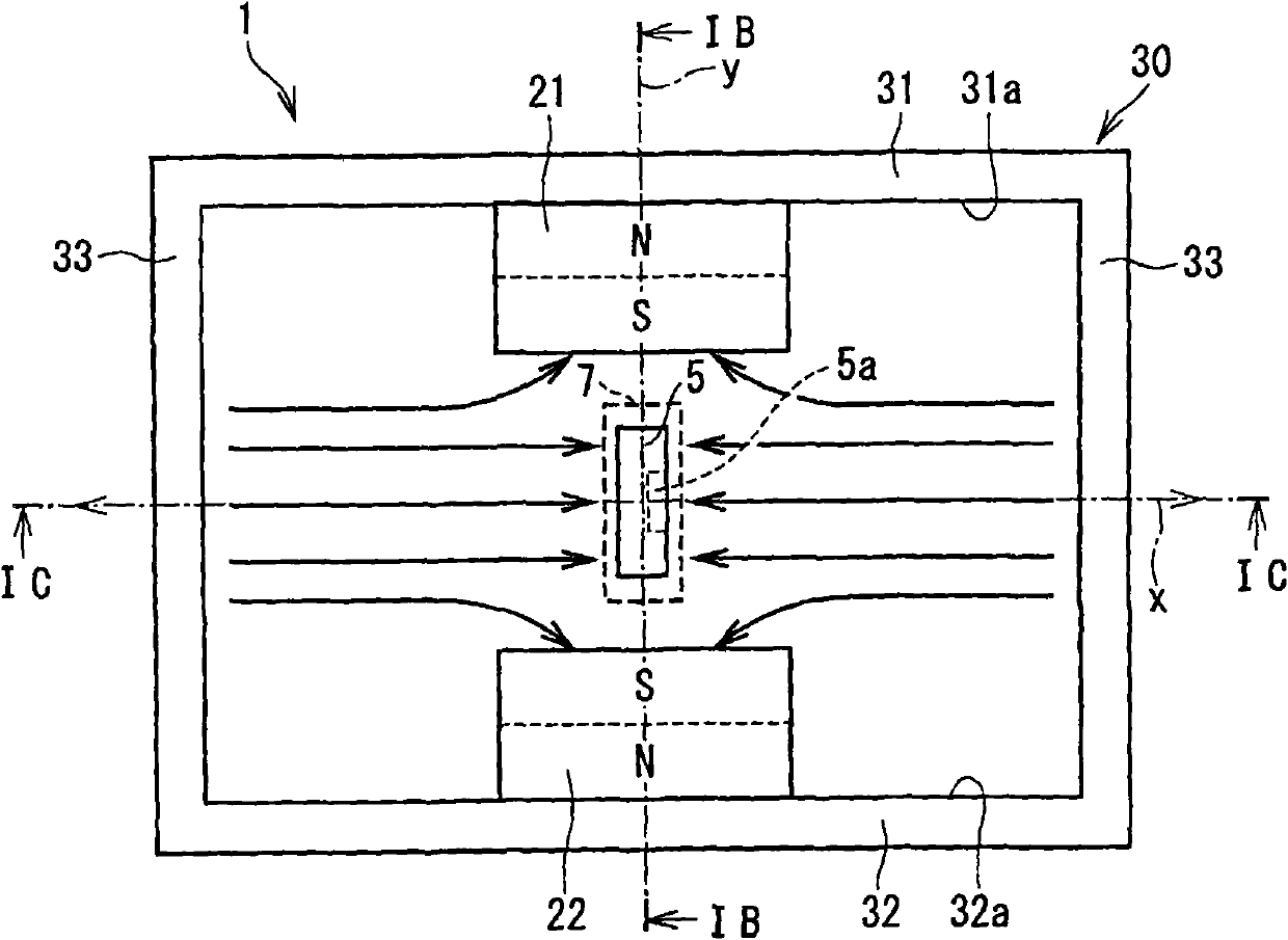
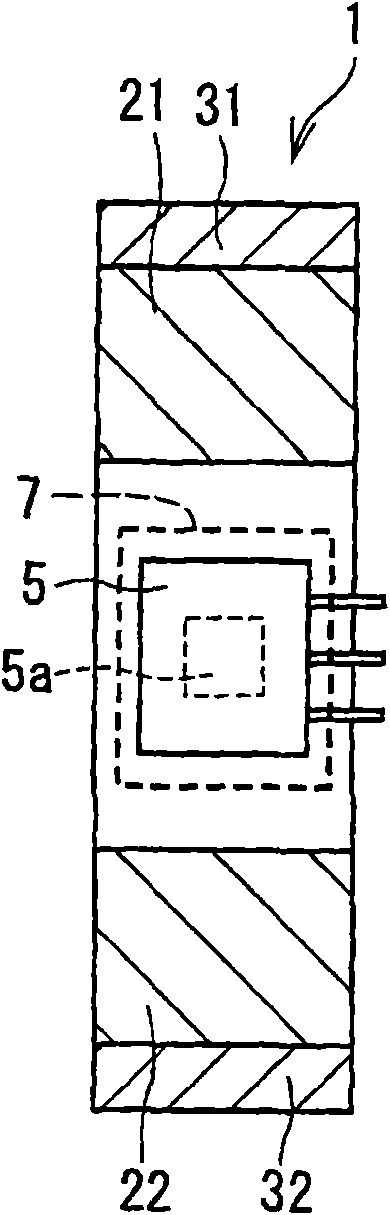
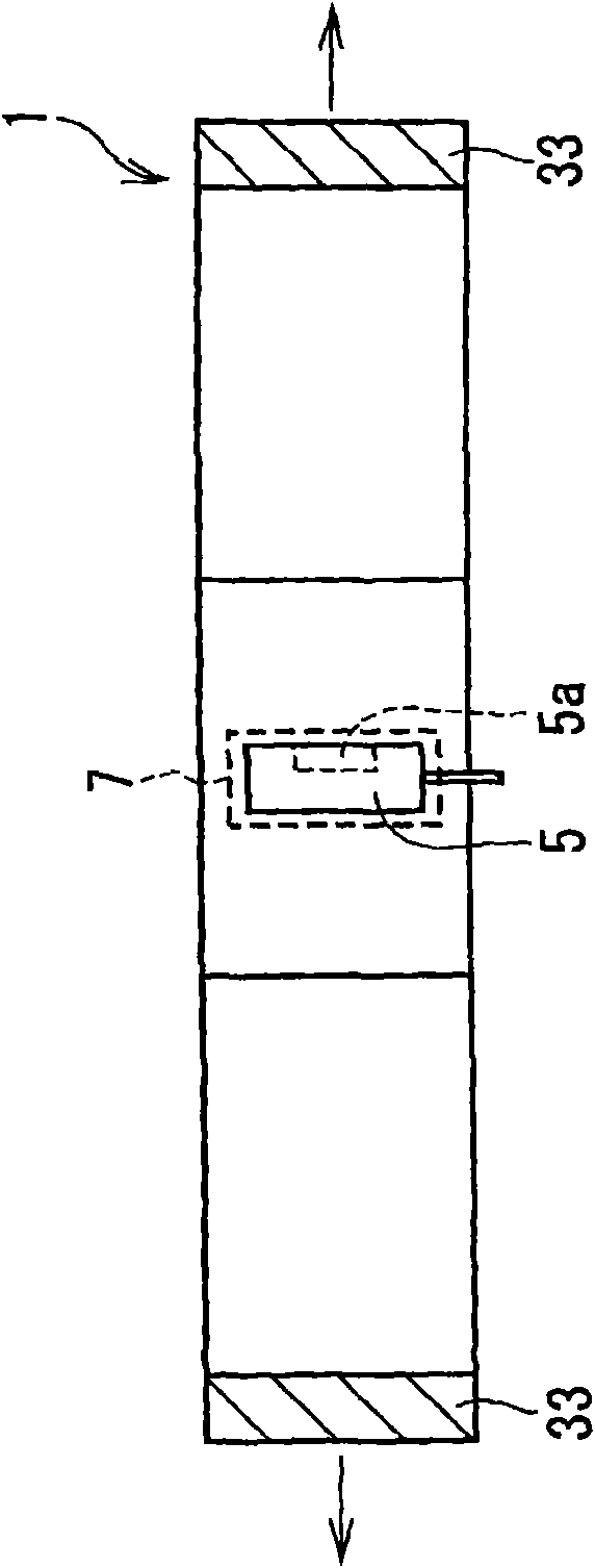
[0048] refer to figure 2 The stroke amount detection device 1 according to the first embodiment generally includes a first magnet 21 and a second magnet 22 as examples of first and second magnetic field generating members and a Hall element 5 as an example of a first sensor element. The Hall element 5 moves relative to the first magnet 21 and the second magnet 22 according to the linear movement of the traveling member 3a of the linear actuator 3 so as to detect the stroke amount.

[0049] The detected stroke amount is sent to an engine control unit (ECU) 10 . The ECU 10 performs feedback control of the linear brake 3 using the detected stroke amount.

...

no. 2 example

[0076] will refer to Figure 5 and 6 The second embodiment will be described.

[0077] refer to Figure 5 , the stroke detection device 1 according to the second embodiment has a first magnet 25 and a second magnet 26 instead of the first magnet 21 and the second magnet 22 of the first embodiment. Each of the first magnet 25 and the second magnet 26 has a concave shape including a thin portion 25a, 26a and a thick portion 25b, 26b at opposite sides of the thin portion 25a, 26a.

[0078] The thin portion 25a is provided at the middle position of the stroke range, that is, in the range including the Y-axis. The thick portion 25b is provided on the opposite side of the thin portion 25a with respect to the stroke direction. The thickness of each of the thick portions 25b is larger than the thickness of the thin portions 25a with respect to the Y direction. Therefore, the distance between the thick portion 25b and the surface and the X-axis is smaller than the distance between...

no. 3 example

[0084] will refer to Figure 7 , 8A and 8B to describe the third embodiment. In the stroke detection device 1 according to the third embodiment, as Figure 7 As shown, the first magnet 21 and the second magnet 22 deviate from the Y axis to the negative side of the travel direction, that is, deviate to Figure 7 in the left side.

[0085] For example, in the case of biasing the travel range of the traveling object toward the negative side from the reference point, the first magnet 21 and the second magnet 22 are disposed on the negative side so as to be adjacent to the center of the travel range. Therefore, since the point where the magnetic flux density is zero is centered, an accurate range can be selectively utilized.

[0086] exist Figure 7 , arrow Le represents a detectable range (detection applicable range) in which the magnetic flux density can be detected by the Hall element 5 and an arrow Lu represents an undetectable range in which the magnetic flux density cann...


PUM


Abstract

A stroke amount detecting device includes a first magnetic field generation member (21, 25), a second magnetic field generation member (22, 26), and a magnetic sensor unit (7, 8). The first magnetic field generation member (21, 25) and the second magnetic field generation member (22, 26) are opposed to each other with respect to a direction perpendicular to a straight stroking axis of a stroking object, and magnetized in opposite directions. The magnetic sensor unit (7, 8) is movable in an area between the first magnetic field generation member (21, 25) and the second magnetic field generation member (22, 26), along a straight traveling axis (X) that is parallel to the straight stroking axis relative to the first magnetic field generation member (21, 25) and the second magnetic field generation member (22, 26) in accordance with a stroke motion of the stroking object. The magnetic sensor unit (7, 8) has a magnetosensitive surface (5a, 6a) facing a direction parallel to the traveling axis (X), thereby to detect an amount of stroke of the object.

Description

technical field [0001] The present invention relates to a stroke amount detecting device for detecting the stroke amount of a traveling object. Background technique [0002] In a conventional stroke amount detection device, a magnetic sensor element moves relative to a magnet as a magnetic field generating member according to a linear motion of a traveling object. The amount of travel of the object is detected based on an output signal generated from the magnetic sensor element. For example, JP2000-180114A and JP2008-45919A corresponding to US6211668 describe inventions for improving the linearity of an output signal with respect to the stroke amount. [0003] In the magnetic position sensor described in JP2000-180114A, conical magnets face each other in a direction parallel to the line along which the magnetic sensor element moves. Likewise, opposing conical magnets are provided on both sides of the travel range of the magnetic sensor element, eg on a first side and a sec...

Claims


Application Information

Patent Timeline
Patent Type & Authority Applications(China)
IPC IPC(8): G01B7/00G01B7/02G01D5/12
CPCG01D5/145
Inventor 松本光一郎河野祯之本多仁美
Owner DENSO CORP
Why Eureka
Try Eureka