
Semiconductor reflection type optical fiber temperature sensor

A fiber optic temperature and semiconductor technology, applied in the field of temperature sensing, can solve problems such as poor linearity, low precision, and inaccurate temperature measurement

Inactive Publication Date: 2011-11-09
SHANGHAI BOOM FIBER SENSING TECH
View PDF3 Cites 4 Cited by
  • Summary
  • Abstract
  • Description
  • Claims
  • Application Information

AI Technical Summary

Problems solved by technology

[0004] However, since the semiconductor wafer and the end face of the conductive fiber core are physically connected under the pressure of the spring, there is a distance between the two and the distance will be changed by changes in the external environment, resulting in changes in the reflected light intensity, making Inaccurate temperature measurement, poor linearity, low precision

Method used


Image

  • Semiconductor reflection type optical fiber temperature sensor
  • Semiconductor reflection type optical fiber temperature sensor
  • Semiconductor reflection type optical fiber temperature sensor

Examples


Embodiment 1

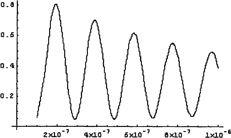
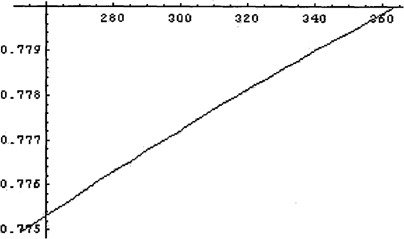
[0023] Embodiment 1: One end of the optical fiber 1 is inserted into the ceramic ferrule 4, so that the end face of the fiber core and the end face of the ceramic ferrule 4 are on the same plane, and the plane is plated with a germanium layer 3 with a thickness of 100 nm by ion-assisted evaporation method. The curve of the reflected optical power with temperature is shown as figure 2 shown. After the laser hits the germanium layer 3, according to the current temperature, the germanium layer 3 will correspond to a kind of reflected optical power. After receiving the reflected optical power, after photoelectric conversion, signal amplification, and AD conversion, the current near the germanium layer 3 can be obtained. temperature.

Embodiment 2

[0024] Embodiment 2: One end of the optical fiber 1 is inserted into the ceramic ferrule 4, so that the end face of the fiber core and the end face of the ceramic ferrule 4 are on the same plane, and the plane is plated with a germanium layer 3 with a thickness of 300 nm by ion-assisted evaporation. At this time, the reflected light power varies with temperature as shown in image 3 shown. After the laser hits the germanium layer 3, according to the current temperature, the germanium layer 3 will correspond to a kind of reflected optical power. After receiving the reflected optical power, after photoelectric conversion, signal amplification, and AD conversion, the current near the germanium layer 3 can be obtained. temperature.

Embodiment 3

[0025] Embodiment 3: One end of the optical fiber 1 is inserted into the ceramic ferrule 4, so that the end face of the fiber core and the end face of the ceramic ferrule 4 are on the same plane, and the surface is coated with a germanium layer 3 with a thickness of 500 nm by using coating technology, and the reflected The variation curve of optical power with temperature is shown as Figure 4 shown. After the laser hits the germanium layer 3, according to the current temperature, the germanium layer 3 will correspond to a kind of reflected optical power. After receiving the reflected optical power, after photoelectric conversion, signal amplification, and AD conversion, the current near the germanium layer 3 can be obtained. temperature. A ceramic sleeve 2 is packaged outside the ceramic pin. This ceramic sleeve 2 can protect the germanium layer 3 and at the same time form a temperature detection cavity with the surface of the germanium layer 3. When the external environment...


PUM

PropertyMeasurementUnit
Thicknessaaaaaaaaaa

Abstract

The invention discloses a temperature sensor, and particularly relates to a semiconductor reflection type optical fiber temperature sensor. The optical fiber temperature sensor comprises an optical fiber, a semiconductor film and a ceramic pin, wherein the optical fiber core is inserted into the ceramic pin to ensure that the end face of the fiber core and the end face of the ceramic pin are in the same plane; the semiconductor film is coated to the plane by adopting a film coating technology, the film coating technology ensures that the semiconductor film and the optical fiber are closely connected, and the refractive rate of the semiconductor is not influenced by external pressure, vibration and the like, so that the temperature measurement accuracy is greatly improved; the ceramic pin can fix the optical fiber core, and increase the area of the semiconductor film, so that the semiconductor film and the optical fiber are closely contacted; and a ceramic sleeve is encapsulated outside the film coated ceramic pin, can protect the coated film, and form a temperature detection cavity with the semiconductor film surface, and when the temperature of the external environment is changed, the semiconductor film is heated uniformly, and the detected temperature is accurate.

Description

technical field [0001] The invention relates to the technical field of temperature sensing, in particular to a semiconductor reflection optical fiber temperature sensor. Background technique [0002] In the past, semiconductor absorption fiber optic temperature sensors mostly used gallium arsenide sensitive materials, 850nm light source and multimode optical fiber and other structures. This structure makes it difficult to improve and reduce the structure and volume of the sensor, and the measurement accuracy is not high. [0003] In a patent document with application number 200910062879.1 published by the State Intellectual Property Office of the People's Republic of China, a semiconductor reflective optical fiber temperature sensor and its sensing device are disclosed. In this sensor, a semiconductor chip is pressed against one end of the conductive optical fiber with a spring to provide a semiconductor reflection optical fiber temperature sensor, which overcomes the short...

Claims


Application Information

Patent Timeline
IPC IPC(8): G01K11/32
Inventor 李旭齐龙舟皋魏席刚仝芳轩周正仙
Owner SHANGHAI BOOM FIBER SENSING TECH
Learn More