
Optical fiber sensor for detecting strain and temperature change simultaneously

A fiber optic sensor and temperature measuring fiber technology, which can be applied in the direction of measuring the change of optical properties of materials when they are stressed, thermometers and instruments with physical/chemical changes, etc. It can improve the measurement sensitivity, simple processing technology and stable and reliable work.

Active Publication Date: 2011-11-09
SHANGHAI GAOSHI PHOTOELECTRIC CO LTD
View PDF3 Cites 24 Cited by
  • Summary
  • Abstract
  • Description
  • Claims
  • Application Information

AI Technical Summary

Problems solved by technology

However, epoxy resin glue has the following defects: (1) when not toughened, the cured product is generally brittle, with poor peeling resistance and impact resistance; (2) for materials with little polarity (for example, polyethylene, polypropylene , fluoroplastics, etc.) have low adhesion and must be treated with surface activation; (3) Some raw materials such as reactive diluents, curing agents, etc. have varying degrees of toxicity and irritation; It is prone to failure or poor performance in a humidity environment (for example, the adhesive force becomes smaller), which will cause the wavelength creep of the sensor itself, thereby interfering with the judgment of the strain change of the actual measured object
Therefore, the optical fiber sensor encapsulated with epoxy resin glue in the prior art has a durability problem that is difficult to overcome, and the service life generally does not exceed 2 years

Method used


Image

  • Optical fiber sensor for detecting strain and temperature change simultaneously
  • Optical fiber sensor for detecting strain and temperature change simultaneously
  • Optical fiber sensor for detecting strain and temperature change simultaneously

Examples


Embodiment Construction

[0035] The present invention will be described in further detail below in conjunction with the accompanying drawings and specific embodiments.

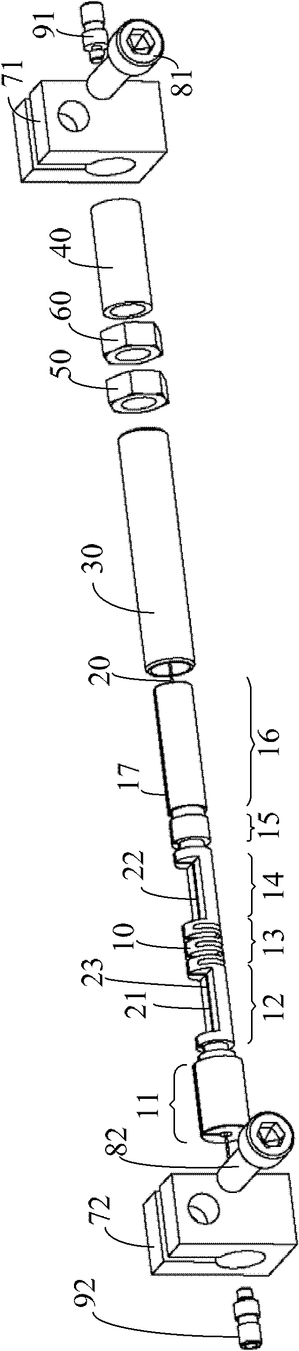
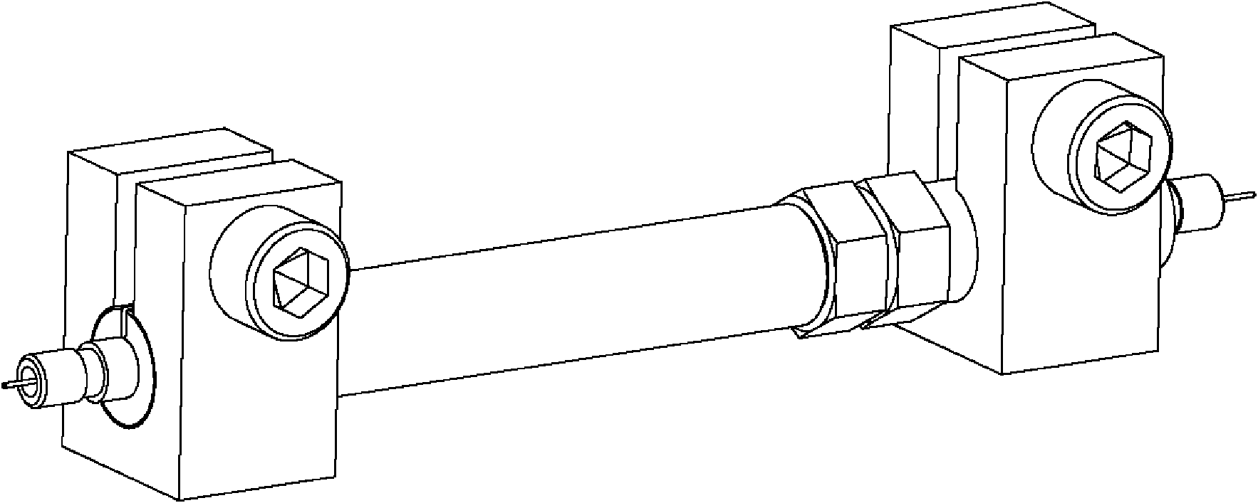
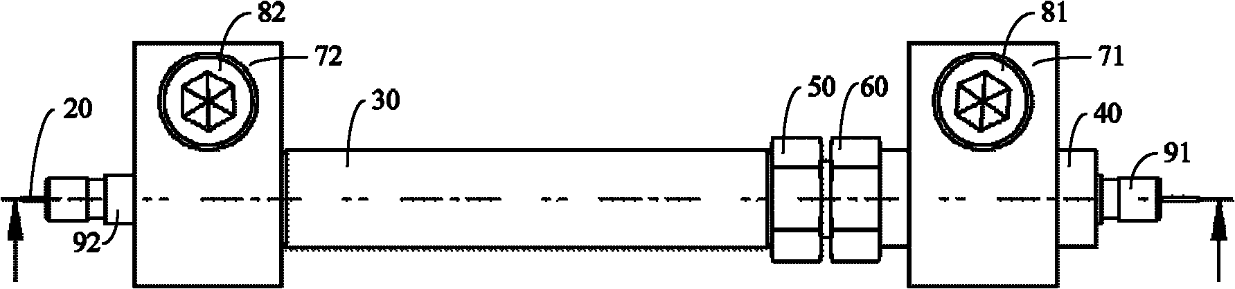
[0036] figure 1 It is a structural exploded diagram of an embodiment of the optical fiber sensor of the present invention. figure 2 is a perspective view of an embodiment of an optical fiber sensor of the present invention. image 3 It is the assembled front view of the embodiment of the optical fiber sensor of the present invention. Figure 4It is an embodiment of the optical fiber sensor of the present invention according to image 3 Section view in the direction of the hatching. Figure 5 It is the left side view after assembly of the fiber optic sensor embodiment of the present invention. Figure 6 It is the right side view after assembly of the fiber optic sensor embodiment of the present invention.

[0037] like Figure 1-6 As shown, the optical fiber sensor among the present invention comprises: elastic beam 10, optical ...


PUM


Abstract

The invention discloses an optical fiber sensor for detecting strain and a temperature change simultaneously. The optical fiber sensor comprises an optical fiber and an elastic beam, wherein a first Bragg micro grating part and a second Bragg micro grating part are arranged on the optical fiber at intervals of a predetermined distance; a difference exists between the wavelengths of the first Bragg micro grating part and the second Bragg micro grating part; the elastic beam comprises a temperature measuring optical fiber bearing area, a strain measuring optical fiber bearing area and an elastic telescopic area positioned between the temperature measuring optical fiber bearing area and the strain measuring optical fiber bearing area; the first Bragg micro grating part of the optical fiber is arranged on the temperature measuring optical fiber bearing area in a free state; and the optical fiber positioned between the first Bragg micro grating part and the second Bragg micro grating part is continuously fixed on the elastic telescopic area and the temperature measuring optical fiber bearing area. The optical fiber sensor can perform temperature and strain sensing detection, has low cost and high mechanical strength, and works stably and reliably, and the preparation process is simple.

Description

technical field [0001] The invention relates to an optical fiber sensor device, in particular to an optical fiber sensor for simultaneously measuring dual parameters of temperature change and stress change. Background technique [0002] Optical fiber sensor is an eye-catching and very important type of sensor device in optical fiber sensor. Using optical fiber sensor can measure the stress and temperature change of steel structure / concrete structure. At the same time, because the optical fiber sensor uses optical signals for detection and transmission, it can realize any scale of networking through wavelength division multiplexing technology, so as to perform large-scale monitoring and measurement. Therefore, this technology is widely used in the field of measurement and control technology, especially in construction. , Petroleum, mining, chemical industry, electric power, transportation and other industries have been widely used. [0003] The basic principle of optical fib...

Claims


Application Information

Patent Timeline
Patent Type & Authority Applications(China)
IPC IPC(8): G01K11/32G01L1/24G01B11/16G01K11/3206
Inventor 徐峻锋殷秀萍
Owner SHANGHAI GAOSHI PHOTOELECTRIC CO LTD
Features
  • Generate Ideas
  • Intellectual Property
  • Life Sciences
  • Materials
  • Tech Scout
  • Unparalleled Data Quality
  • Higher Quality Content
  • 60% Fewer Hallucinations
Learn More