Method for testing heat resistance of radiator

A test method and radiator technology, applied in the direction of thermal development of materials, can solve the problems of inaccurate results and results errors, and achieve the effect of simplifying the experimental method, lowering the power requirement, and reducing the test cost.

Inactive Publication Date: 2011-11-09
LG ELECTRONICS (TIANJIN) APPLIANCES CO LTD
View PDF0 Cites 17 Cited by
  • Summary
  • Abstract
  • Description
  • Claims
  • Application Information

AI Technical Summary

Problems solved by technology

[0011] However, the existing thermal resistance calculation method requires the power P of the heating source to be known, and the power P must be constant during the heating process, even if there is a small fluctuation

Method used


Image

  • Method for testing heat resistance of radiator
  • Method for testing heat resistance of radiator
  • Method for testing heat resistance of radiator

Examples


Embodiment Construction

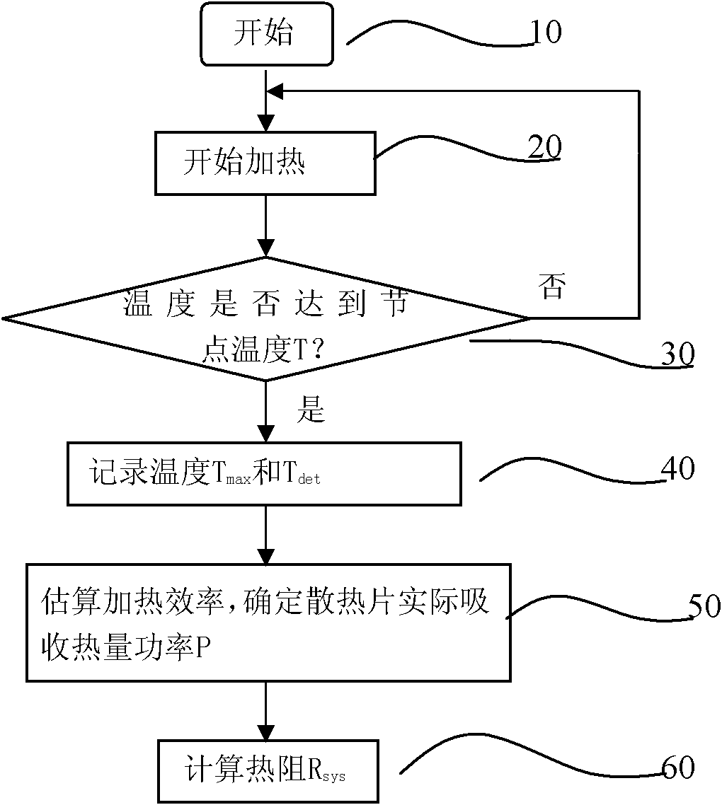
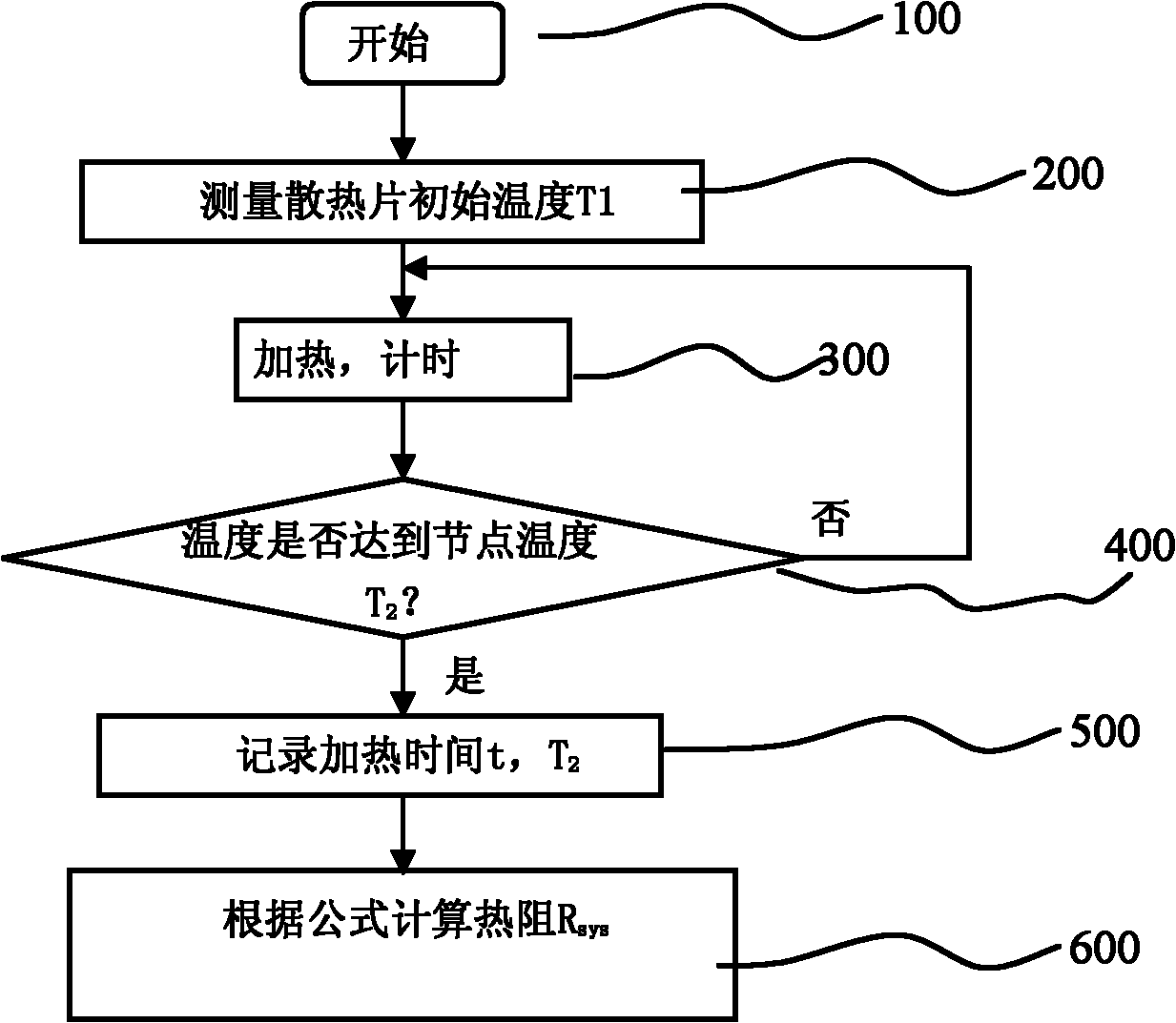
[0026] Below in conjunction with accompanying drawing and specific embodiment, thermal resistance calculation method of the present invention is described in further detail: at first, by Joule's law: Q=I 2 Rt = Pt (2)

[0027] Specific heat capacity: Q=CmΔT=Cm(T 2 -T 1 )(3)

[0028] Formula (2) and formula (3) can be deduced:

[0029] Substituting formula (4) into formula (1), we can get:

[0030] R sys = ( T 2 - T det ) t CmΔT = ( T 2 T det ) t Cm ( ...


PUM


Abstract

The invention relates to a method for testing the heat resistance of a radiator, which comprises the following steps of: (1) arranging a heat source at the bottom of the radiator to be tested and temperature acquisition points in and above the bottom center of the radiator simultaneously, and measuring the temperature T1 of the radiator before the radiator is heated; (2) heating the radiator and timing (in a step 300); (3) continuously heating the radiator until the temperature in the bottom center of the radiator reaches T2 which is slightly higher than the node temperature of a power device using the radiator, measuring and recording T2 and a test point temperature Tdet, and recording heating time t; and (4) respectively substituting the numerical values into a formula, and calculating the heat resistance of the radiator to be tested, wherein C is the specific heat capacity of the radiator, and m is the mass of the radiator. By the heat resistance testing method, an experiment method is simplified, the requirement on the heat source and power thereof is low, testing cost is reduced, the heating efficiency of the heat source is not required to be estimated, and the accuracy of an experiment result is improved.

Description

technical field [0001] The invention relates to a method for testing the thermal resistance of a novel radiator. Background technique [0002] An air conditioner is a device that makes its internal refrigerant undergo a refrigeration or heating cycle consisting of a compression process, condensation process, expansion process, and evaporation process. [0003] Air conditioners are generally divided into ordinary air conditioners and inverter air conditioners according to the compressors installed inside their outdoor units, and both are composed of outdoor units and indoor units. [0004] The outdoor unit of the inverter air conditioner mainly includes a casing that constitutes the top surface and side external structure of the outdoor unit; a chassis that is arranged at the lower end of the casing and on which various components of the outdoor unit can be installed; An inverter compressor and a fixed-speed compressor that compress low-pressure gaseous refrigerant into high...

Claims


Application Information

Patent Timeline
IPC IPC(8): G01N25/20
Inventor 王东东赵馨
Owner LG ELECTRONICS (TIANJIN) APPLIANCES CO LTD
Why Eureka
Try Eureka