Dynamic gas distribution system for standard gas

A standard gas and dynamic gas distribution technology, which is applied in the direction of gas and gas/steam mixing, mixer accessories, dissolution, etc., can solve the problem of large consumption of diluted gas

Inactive Publication Date: 2011-11-16
NAT INST OF METROLOGY CHINA
View PDF8 Cites 10 Cited by
  • Summary
  • Abstract
  • Description
  • Claims
  • Application Information

AI Technical Summary

Problems solved by technology

However, when configuring a smaller concentration of standard gas (for example, about 10 -9 ~10 -6 mol / mol concentration), need to consume a large amount of diluent gas such as pure nitrogen

Method used


Image

  • Dynamic gas distribution system for standard gas
  • Dynamic gas distribution system for standard gas
  • Dynamic gas distribution system for standard gas

Examples


Embodiment 1

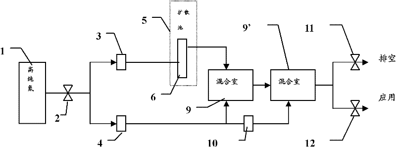
[0030] Example 1: Using figure 1 A dynamic gas distribution device to configure hydrogen sulfide standard gas of about 100ppb in high-purity nitrogen

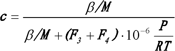
[0031] Using high-purity nitrogen as the carrier gas and dilution gas source 1, the high-purity nitrogen passes through the pressure regulator valve 2 to control the pressure; the mass flow controller 3 controls the flow of the carrier gas passing through the diffusion cell 5; the mass flow controller 4 controls the flow of the dilution gas; Hydrogen sulfide permeation pipe 6 is placed in the diffusion cell 5 of 35 ℃, and its permeation rate is 0.425 μ g / min; Flow regulating valve 10 controls the dilution gas flow rate that enters mixing chamber 9 '; Therefore the hydrogen sulfide concentration of outlet 11 and 12 can be Obtained by the following calculation:

[0032] c = β / M β / M ...

Embodiment 2

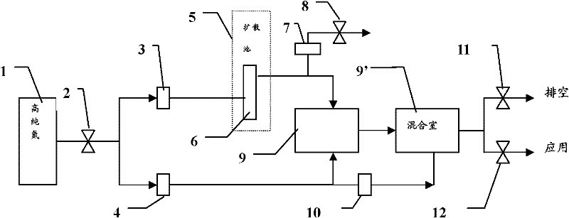
[0046] Example 2: Using figure 2 A dynamic gas distribution device to configure about 400ppb hydrogen sulfide standard gas in high-purity nitrogen

[0047] Using high-purity nitrogen as the carrier gas and dilution gas source 1, the high-purity nitrogen passes through the pressure regulator valve 2 to control the pressure; the mass flow controller 3 controls the flow of the carrier gas passing through the diffusion cell 5; the mass flow controller 4 controls the flow of the dilution gas; The flow controller 7 controls the forced vent flow; the hydrogen sulfide permeation tube 6 is placed in the diffusion cell 5 at 45°C, and its permeation rate is 0.763 μg / min; the flow regulating valve 10 controls the dilution gas flow into the mixing chamber 9'.

[0048] The mass rate of hydrogen sulfide entering the mixing chamber 9 is calculated by the following formula:

[0049] q = β M · F ...

Embodiment 3

[0053] Example 3: Using figure 2 A dynamic gas distribution device to configure about 200ppb hydrogen sulfide standard gas in high-purity nitrogen

[0054] Operation and parameter are the same as embodiment 2, just change following parameter: carrier gas flow rate F 3 =100ml / min, dilution gas flow F 4 =1000ml / min, vent flow F 7 =60ml / min; the flow regulating valve 10 controls the part of the dilution gas flow entering the mixing chamber 9' to be about 600ml / min. Results: The theoretical concentration of hydrogen sulfide standard gas at outlets 11 and 12 is 207.9ppb; the concentration of gas at outlet 12 is analyzed by a total sulfur analyzer, and the concentration is 203.8ppb, and the relative deviation between the two is 2.0%.


PUM


Abstract

The invention provides a dynamic gas distribution system for producing a standard gas mixture in the concentration range of between 10<-9> and 10<-6> mol / mol. In the system, a diffusion tube containing a target substance is arranged in a diffusion pond of which the temperature is controlled; carrier gas with preset flow flows through the diffusion pond containing the target substance, so that the carrier gas carries the target substance to flow out of the diffusion pond; the carrier gas carrying the target substance flows into a first mixed chamber in at least two mixed chambers; diluted gas with preset flow is divided into at least two diluted gas branch gas flows; a first diluted gas branch gas flow flows into the first mixed chamber and is mixed with the carrier gas flowing into the mixed chamber, and first mixed gas formed by mixing flows into a second mixed chamber; and a second diluted gas branch gas flow flows into the second mixed chamber and is mixed with the first mixed gas so as to obtain the standard gas mixture, which has the required concentration, of the target substance.

Description

technical field [0001] The present invention relates to a kind of dynamic gas distribution system of standard gas, more specifically relate to a kind of utilizing diffusion tube or permeation tube to produce (about 10 -9 ~10 -6 ) Dynamic gas distribution system for standard gas mixtures in the mol / mol concentration range. Background technique [0002] In many industrial applications, for low concentrations of standard gases (such as 10 -9 ~10 -6 mol / mol concentration range) is in increasing demand. At present, there are mainly two methods for preparing low-concentration standard gas mixtures, namely static method and dynamic method. The static method is to use weighing or pressure to prepare a certain concentration of the desired mixture, and then hold it in a container for use. The dynamic method is to introduce the target component into a pure diluent gas stream at substantially atmospheric pressure, obtain the desired concentration, and then use it in a specific appl...

Claims


Application Information

Patent Timeline
IPC IPC(8): B01F15/04B01F3/02B01F23/10
Inventor 胡树国吴海韩桥刘新志
Owner NAT INST OF METROLOGY CHINA
Why Eureka
Try Eureka