Positioning delay control device for continuous automation production of stainless steel heddle

A time-delay control, stainless steel technology, applied in applications, household appliances, other household appliances, etc., can solve the problems of many stamping processes, difficult to achieve, poor product consistency, etc., to achieve smooth heald surface, high production efficiency, and energy consumption reduction effect

Inactive Publication Date: 2013-08-28
林佳贤
View PDF3 Cites 0 Cited by
  • Summary
  • Abstract
  • Description
  • Claims
  • Application Information

AI Technical Summary

Problems solved by technology

[0005] Traditional healds are made of stainless steel. Since the stainless steel material for healds is rolled and slender, in order to achieve the purpose of continuous automatic stamping, it is necessary to solve the problem of continuous and accurate delivery of stainless steel strips in production. However, the existing general-purpose technology is difficult to achieve
For example, cylinder conveying, roller conveying, punch crankshaft conveying, inclined wedge conveying, etc., even if this kind of conveying is equipped with a guide needle, it is difficult to achieve synchronous and accurate conveying of stainless steel strips to multiple stamping equipment
[0006] Therefore, the existing domestic technologies for producing stainless steel healds are all single punching, and the roughness of the product section and the burrs generated are all manually polished.
The healds produced in this way have many stamping processes, poor product consistency, and high labor costs.
In addition, in order to make the yarn lint-free and uninterrupted when the yarn moves in the heald hole, most of the domestic methods use a separate polishing process for the center hole, which is time-consuming and laborious.

Method used


Image

  • Positioning delay control device for continuous automation production of stainless steel heddle
  • Positioning delay control device for continuous automation production of stainless steel heddle

Examples


Embodiment Construction

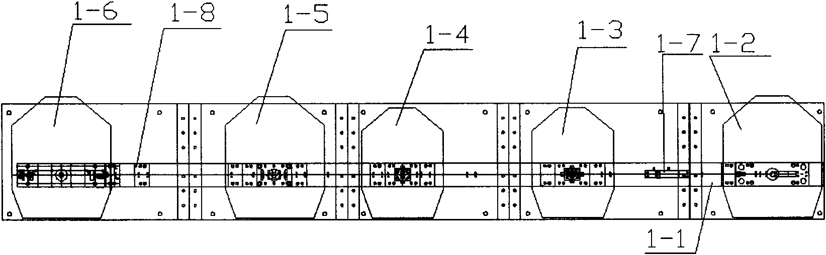
[0023] Such as figure 1 As shown, the present invention provides a continuous automatic production equipment for stainless steel healds, comprising a heald conveying platform 1-1; above the heald conveying platform and along the direction of heald conveying, punching presses 1-2 are arranged respectively , primary chamfering punch 1-3, secondary chamfering punch 1-4, widening hole punch 1-4 and forming punch 1-6; the heald conveying table between the punching punch and the primary chamfering punch is installed with Positioning delay control device 1-7; Straightening traction device 1-8 is arranged on the heald conveying table between the widening hole punch press and the forming punch press.

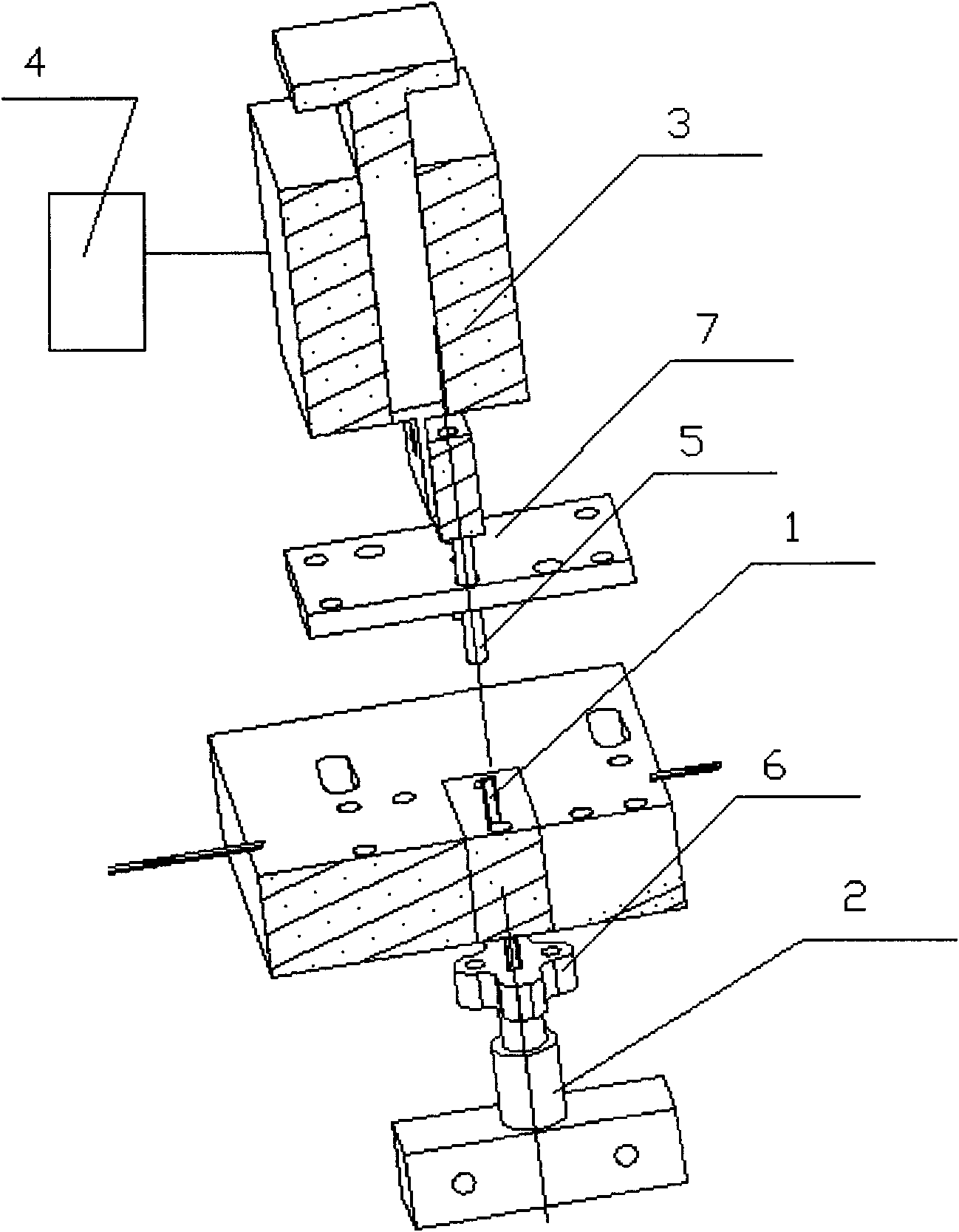
[0024] Such as figure 2 As shown, the positioning delay control device includes a positioning pin 1, a stroke control switch 2 is connected below the positioning pin, and a positioning pin suction device 3 is installed above the positioning pin, and the positioning pin suction device i...


PUM


Abstract

The invention discloses a positioning delay control device for the continuous automation production of a stainless steel heddle, comprising a positioning pin. A stroke control switch is connected under the positioning pin. A positioning pin suction device is installed above the positioning pin. The positioning pin suction device is connected with a delay relay. The stroke control switch and the delay relay are electrically connected with all punching machines of equipment for the continuous automation production of the stainless steel heddle respectively so as to control all punching machines. By means of controls of the delay relay and the stroke control switch, when the stroke control switch is in a closed state; all punching machines are idle so as not to perform punching operation; and, when the stroke control switch is started, all punching machines begin to perform punching operation. In the invention, the continuous automation production of the stainless steel heddle is realized; the yield is improved greatly; the energy consumption is reduced obviously; the quality of the produced heddle is steady; the edge of a punched hole is smooth without burr; the surface of the heddle is flat and smooth; the heddle can slide freely; and the service life of the heddle is long.

Description

technical field [0001] The invention relates to a positioning delay control device for continuous automatic production of stainless steel heddles. Background technique [0002] Heddles are used on looms. There are three ring holes in the upper, middle and lower positions of each heald. The middle ring hole is small and called the middle hole, which is used for threading the yarn warp; of. Hundreds of healds pass through the heddles or hangers to form a heald frame or heddles, which are used in the belly of the loom, like a multi-layer screen seal. The control and warp threads are alternately divided into upper and lower layers of weaving holes, allowing the weft threads to pass through to weave cloth. [0003] Heddles have various specifications, and the specifications used for weaving cotton, hemp, silk, wool, etc. are different. [0004] Healds are a bulky consumable accessory in textile production. China, as a densely populated area of ​​global textile enterprises, co...

Claims


Application Information

Patent Timeline
Patent Type & Authority Patents(China)
IPC IPC(8): B21F45/08
Inventor 林佳贤
Owner 林佳贤
Why Eureka
Try Eureka