Laser gyro optical resonant cavity loss measurement system based on resonance method

A laser gyroscope and resonant cavity technology, applied in the field of measurement, can solve the problems of reducing measurement efficiency, increasing the complexity of the measurement process and measurement cost, and achieving the effects of improving measurement accuracy, filtering out noise interference, and simplifying the measurement process.

Inactive Publication Date: 2013-04-03
XIDIAN UNIV
View PDF2 Cites 0 Cited by
  • Summary
  • Abstract
  • Description
  • Claims
  • Application Information

AI Technical Summary

Problems solved by technology

The current general measurement method is: in addition to the resonant cavity loss measurement system, an additional set of special measurement devices is added to measure and correct the nonlinearity of piezoelectric ceramics. This measurement system not only increases the complexity and cost of the measurement process , and reduces the measurement efficiency

Method used


Image

  • Laser gyro optical resonant cavity loss measurement system based on resonance method
  • Laser gyro optical resonant cavity loss measurement system based on resonance method
  • Laser gyro optical resonant cavity loss measurement system based on resonance method

Examples


Embodiment Construction

[0022] The system structure of the present invention will be described in detail below in conjunction with the accompanying drawings.

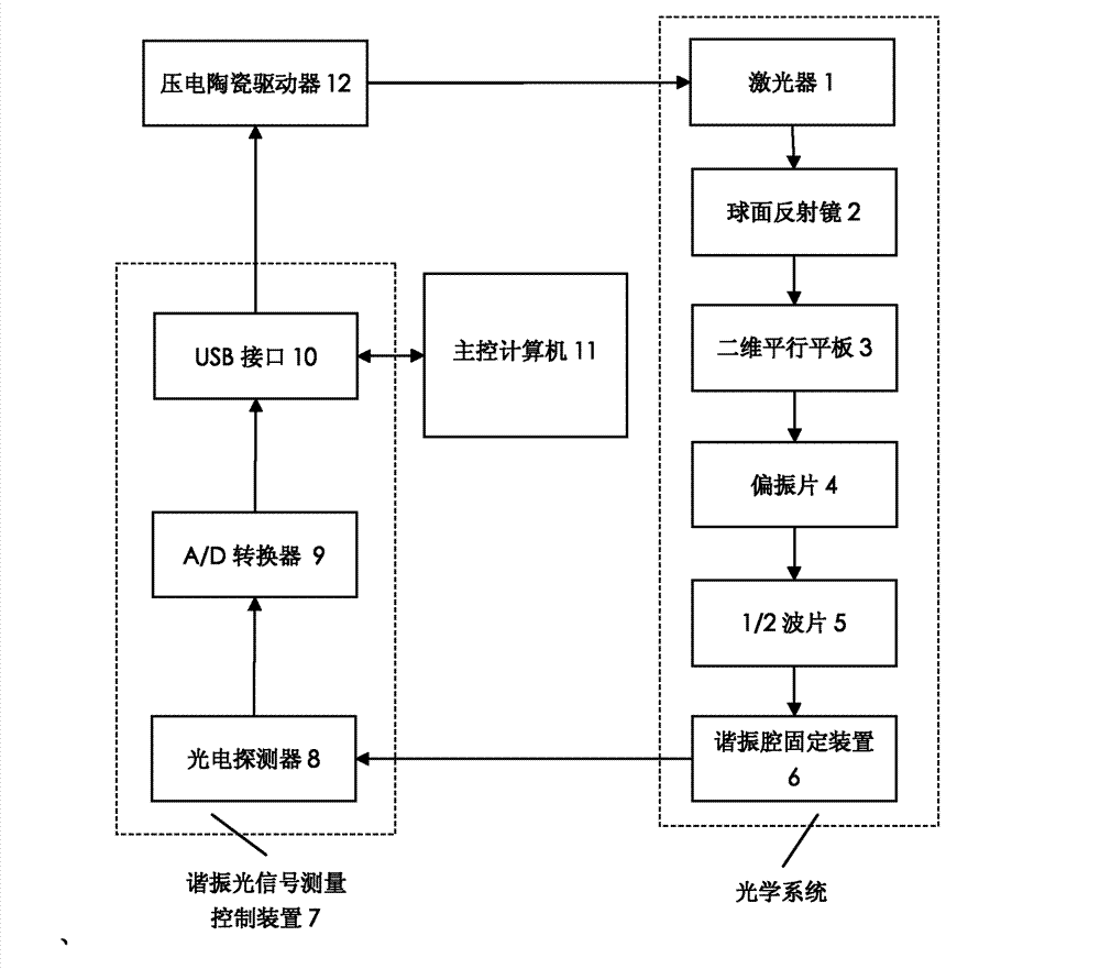
[0023] refer to figure 1 , the measurement system of the present invention includes an optical system, a resonant optical signal measurement control device 7, a main control computer 11 and a piezoelectric ceramic drive circuit 12, the optical system generates an optical signal, and transmits the optical signal to the main control computer through the resonant optical signal measurement control device 7 11. The main control computer 11 simultaneously controls the piezoelectric ceramic drive circuit 12 through the resonant optical signal measurement control device 7, and applies a drive voltage and a bias voltage to the optical system. in:

[0024] The optical system includes a laser 1, a spherical mirror 2, a two-dimensional parallel plate 3, a polarizer 4, a 1 / 2 wave plate 5 and a resonant cavity fixing device 6. The laser 1 adopts a single-...


PUM


Abstract

The invention discloses a laser gyro optical resonant cavity loss measurement system which mainly solves the problem that the traditional measurement system needs additional systems to complete nonlinear correction of piezoelectric ceramics. The whole measurement system comprises a laser (1), a spherical reflector (2), a two-dimensional parallel flat plate (3), a polaroid (4), a 1 / 2 wave plate (5), a resonant cavity fixing device (6), a resonance optical signal measurement control device (7), a main control computer (11) and a piezoelectric ceramic driver (12), wherein the laser emits a laserbeam, and the laser beam enters a laser gyro resonant cavity to be measured through the spherical reflector, the two-dimensional parallel flat plate, the polaroid and the 1 / 2 wave plate and generatesa resonance light, nonlinearity on the piezoelectric ceramics is accurately corrected by applying different bias voltages to the piezoelectric ceramics, and then the resonant cavity loss is figured out through measuring full width at half maximum of a resonant light power spectral line. The invention has the advantages of high efficiency, low cost and accuracy in measurement, and is suitable for high-precision measurement on laser gyro resonant cavity loss.

Description

technical field [0001] The invention belongs to the technical field of measurement, and relates to a measurement system of an optical resonant cavity, which is mainly used for measuring the loss of the optical resonant cavity of a laser gyroscope. Background technique [0002] At present, there are two main methods for measuring the loss of the laser gyro optical resonator: one is the cavity ring-down method based on the measurement of the resonator decay time constant, and the other is the resonance method based on the measurement of the free spectral range of the resonator. The optical cavity ring down method is not affected by the stability of the incident laser beam light intensity of the resonator, but it can only measure lower losses, and the measurement accuracy is reduced for higher losses; while the resonance method is generally used for middle and high Accurate measurement of losses. In addition, there is a direct measurement method based on the DF transflectomete...

Claims


Application Information

Patent Timeline
Patent Type & Authority Patents(China)
IPC IPC(8): G01M11/02G01C25/00
Inventor 邵晓鹏马菁汀陈朝康林见杰王杨钟宬许宏涛黄远辉王阳杨晓晖
Owner XIDIAN UNIV
Why Eureka
Try Eureka