Ecological permeable stratal configuration

An ecological and stratigraphic technology, applied in the field of stratum structure and ecological permeable stratum structure, can solve the problems of destroying the climate, depletion, and difficulty in improving the urban agglomeration range, and achieve the effects of solving the heat island effect, solving urban water accumulation, and reducing temperature

Active Publication Date: 2011-11-23
ZHEJIANG FANGYUAN BUILDING MATERIALS TECH
7 Cites 26 Cited by

AI-Extracted Technical Summary

Problems solved by technology

First, because concrete is not water-permeable, the water on the surface of the brick body cannot penetrate into the soil below the concrete, so a large amount of water is prone to be generated on the surface of the ground. Flood disasters; on the other hand, studies have found that since rainwater cannot penetrate into the underground soil for a long time, it will cause the heat island effect in the city, destroy the climate within the urban agglomeration area, and indirectly affect human health; moreover, the underground soil has never had rainwater The infiltration will cause t...

Method used

Basement 3 is provided under stratum, and aquifer comprises the structural layer 4 that is arranged on basement 3 top, and structural layer 4 adopts concrete material structure to strengthen its load-bearing strength, and structural layer 4 plays to basement 3 top load-bearing Frame support. The top of the structural layer 4 is closely pasted with a waterproof layer 5 that is a high-efficiency waterproof material, so it can effectively prevent moisture from continuing to seep until it leaks from the top surface of the basement 3 . In the basement 3 or at the same level as the basement 3, a water storage tank 1 is provided. A drainage pipe 2 and a centrifugal water pump connected to the opening of the drainage pipe 2 are arranged in the inner cavity of the water storage tank 1, and the lower end of the drainage pipe 2 is connected to The mouth is connected to the inner cavity of the water storage tank 1 through a centrifugal water pump, and it extends upward until the upper end of the mouth reaches and communicates w...

Abstract

The invention provides an ecological permeable stratal configuration and belongs to the technical field of water collection and water intaking, and the ecological permeable stratal configuration can be used for solving the problems that because the existing urban surface soil layer is impermeable, moisture exchange and circulation can not be performed between the atmosphere and the soil layer, and after the situation lasts for a long time, the phenomena that the air in cities is extremely humid or extremely dry, and the water in soils below the surface soil layer continuously runs out are caused, thereby destroying urban ecological environments and affecting the human health, and the like. The ecological permeable stratal configuration comprises a surface layer and a water storing layer, wherein the surface layer is permeable and can cover the water storing layer, the water storing layer is arranged below the surface layer and can be used for storing water, and a permeation layer which can guide water flows to permeate downwards is arranged between the surface layer and the water storing layer in an appressed clamping mode. The ecological permeable stratal configuration has a good penetration function, and can achieve the rainwater drainage effect of a road surface; and meanwhile, when the outside is in hot dry climates, rainwater collected in the deep of the stratal configuration can be fed back to the air so as to achieve the effects of humidity adjustment and temperature reduction, thereby effectively solving two serious problems, namely, urban ponding and heat island effect.

Application Domain

Technology Topic

Image

  • Ecological permeable stratal configuration
  • Ecological permeable stratal configuration
  • Ecological permeable stratal configuration

Examples

  • Experimental program(3)

Example Embodiment

[0020] Example one
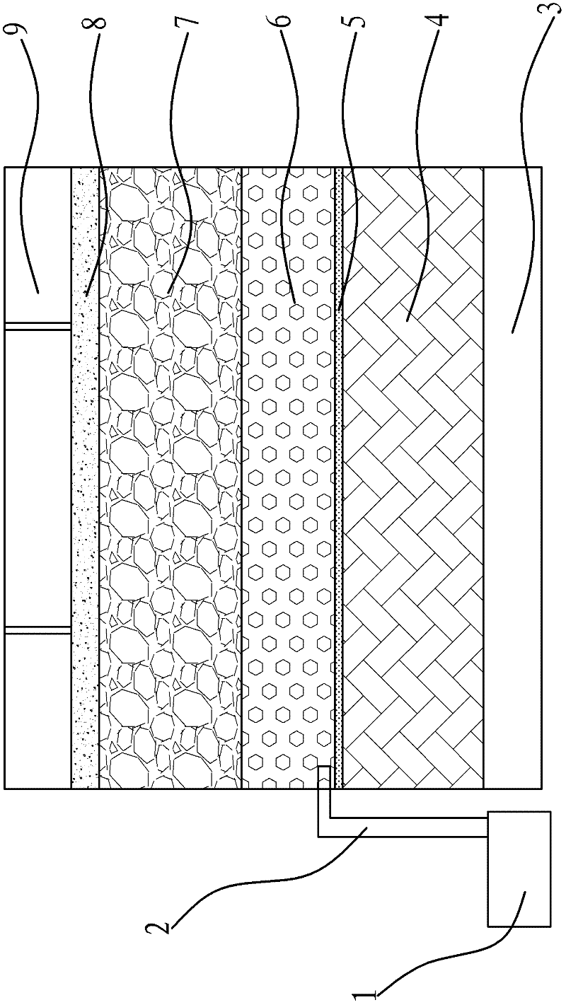
[0021] Such as figure 1 As shown, the ecological permeable stratum structure includes an aquifer, a permeable layer and a surface layer that are laid down in sequence from bottom to top.
[0022] There is a basement 3 under the stratum. The aquifer includes a structural layer 4 laid flat on top of the basement 3. The structural layer 4 is constructed with concrete materials to enhance its load-bearing strength. The structural layer 4 serves as a frame support for the load-bearing above the basement 3. . A waterproof layer 5 made of high-efficiency waterproof material is closely laid on the top of the structural layer 4, so that it can effectively prevent the moisture from continuing to seep down until it leaks from the top surface of the basement 3. In the basement 3 or on the same layer as the basement 3, there is a water storage tank 1. A drainage tube 2 and a centrifugal water pump connected to the opening of the drainage tube 2 are provided in the inner cavity of the storage pool 1, and the lower end of the drainage tube 2 is open The port is connected to the inner cavity of the storage tank 1 through a centrifugal water pump, which extends upward until the upper end port reaches and communicates with the permeable layer laid on the upper side of the waterproof layer 5. The permeable layer includes the ceramsite permeable layer 6 directly laid flat on the upper side of the waterproof layer 5. The ceramsite permeable layer 6 has a large permeability, so it can accelerate the infiltration rate of water, and its thickness is greater than 100mm, and the upper end of the drainage tube 2 is open The port is connected to the bottom of the ceramsite permeable layer 6. The upper side of the ceramsite permeable layer 6 is poured with a permeable concrete permeable layer 7 (strength≥C20) thicker than 150mm. The surface layer laid on the upper side of the permeable layer includes the ecological pavement brick layer 9. First, the cement mung bean mortar with a ratio of 1:4 is laid on the upper side of the permeable concrete permeable layer 7 to a thickness of 30-50mm to form an ecological pavement for bonding The paving layer 8 of the brick layer 9, and then the ecological pavement brick layer 9 is horizontally and closely attached to the paving layer 8.
[0023] When it is in rainy weather, because there are a large number of connected pore structures between the surface layer and the permeable layer, rainwater is easy to seep from the surface layer to the bottom of the permeable layer, and is blocked by the waterproof layer 5 and stagnates above the waterproof layer 5. Then it flows into the drainage tube 2 until it is collected in the cavity of the storage tank 1. At this time, the rainwater seepage collection can reduce the road surface water and keep the road surface clean; in the case of rainy weather or high humidity, no humidity replenishment is required, so storage The rainwater will be kept in the storage tank 1 for a long time; when the outside climate becomes high and dry, the centrifugal water pump set in the storage tank 1 provides driving force, and the rainwater in the cavity is pumped out of the ground to spray the road and vegetation, thus achieving Feed back to the air to adjust the air humidity and lower the atmospheric temperature. This stratigraphic structure solves the two major problems of urban water accumulation and heat island effect.

Example Embodiment

[0024] Example two
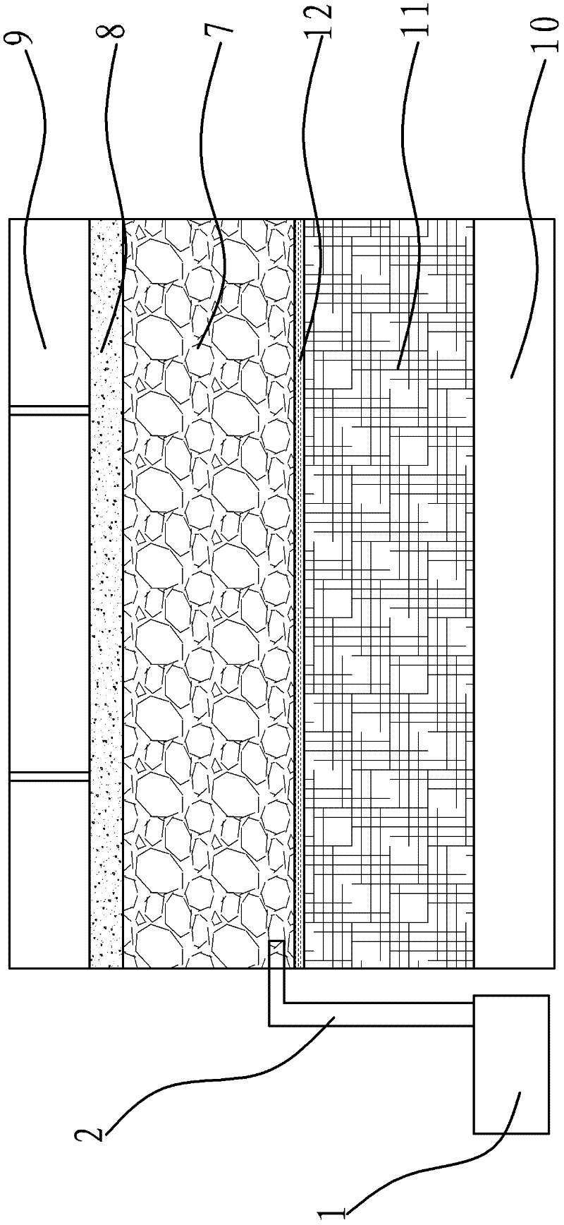
[0025] Such as figure 2 As shown, the structure and principle of this embodiment are basically the same as those of the first embodiment. The difference lies in: the reserved water storage tank 1 is selected at the underground soil layer 10, and the upper side of the underground soil layer 10 adopts pond residue composed of construction waste. After filling and leveling, a pond slag backfill layer 11 is formed. The upper side of the pond slag backfill layer 11 is laid with a relatively inexpensive waterproof geotextile layer 12, and the upper side of the waterproof geotextile layer 12 is poured with permeable concrete thicker than 150mm. Layer 7 (strength ≥ C20), the upper side of the permeable concrete layer 7 is covered with a 30-50mm thick paving layer 8, and finally the ecological pavement brick layer 9 is horizontally pasted on the upper side of the paving layer 8. A drainage pipe 2 is provided between the storage pool 1 and the permeable concrete permeable layer 7 to communicate the two, and a centrifugal water pump connected to the drainage pipe 2 is also provided in the storage pool 1.

Example Embodiment

[0026] Example three
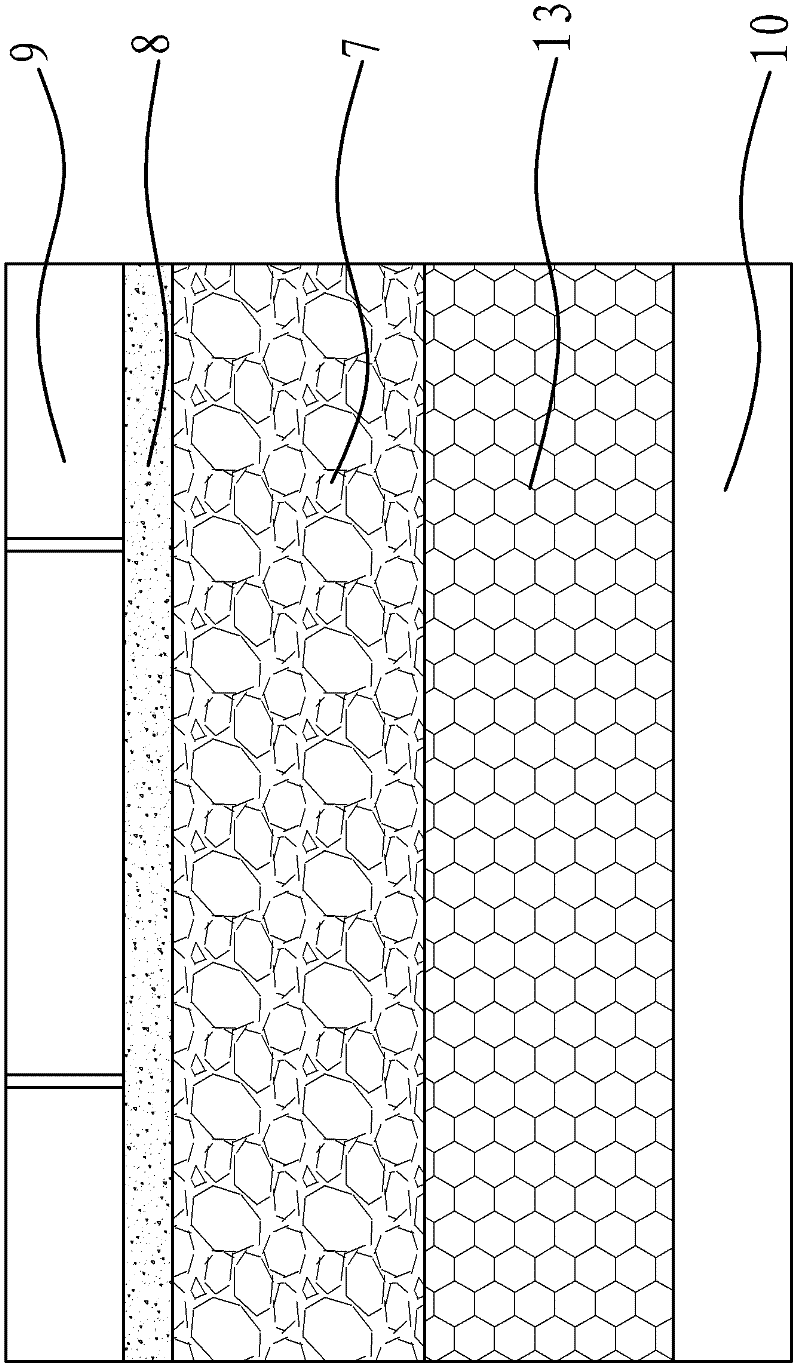
[0027] Such as image 3 As shown, the structure and principle of this embodiment are basically the same as those of the first and second embodiments. The difference lies in: laying sand and gravel on the upper side of the underground soil layer 10 for backfilling compaction and leveling, and the resulting sand The stone water storage layer 13 has appropriate gaps in the particle gradation in the sand and stone water storage layer 13, which on the one hand facilitates the infiltration of rainwater, on the other hand, it can also store rainwater that is too late to seep. The upper side of the sand-gravel water storage layer 13 is closely pasted with a permeable concrete layer 7 (strength ≥C20) greater than 150mm thick, and a 30-50mm thick paving layer 8 is closely pasted on the upper side of the permeable concrete layer 7, and finally The ecological pavement brick layer 9 is horizontally pasted on the upper side of the paving layer 8.
[0028] When it is raining, rainwater infiltrates from the ecological pavement brick layer 9 and the permeable concrete layer 7 to the sandstone water storage layer 13, and most of the rainwater is retained in the sandstone water storage layer 13; When it is at high temperature and dry, the retained rainwater is fed back to the outside air through natural evaporation, which can regulate the humidity and lower the temperature.

PUM

no PUM

Description & Claims & Application Information

We can also present the details of the Description, Claims and Application information to help users get a comprehensive understanding of the technical details of the patent, such as background art, summary of invention, brief description of drawings, description of embodiments, and other original content. On the other hand, users can also determine the specific scope of protection of the technology through the list of claims; as well as understand the changes in the life cycle of the technology with the presentation of the patent timeline. Login to view more.

Similar technology patents

Classification and recommendation of technical efficacy words

Why Eureka
Try Eureka