
Compound differential type long-focus measuring device based on Talbot effect

A measuring device and technology of long focal length, applied in the field of optical testing, can solve the problems of increased measurement influence, difficulty in high-precision measurement, etc., and achieve the effects of compact structure, automatic measurement and data processing, and high measurement accuracy.

Active Publication Date: 2011-11-23
ZHEJIANG UNIV
View PDF2 Cites 13 Cited by
  • Summary
  • Abstract
  • Description
  • Claims
  • Application Information

AI Technical Summary

Problems solved by technology

However, as the focal length increases to tens of meters to tens of meters, most of the current methods need to stretch the beam very long, which is difficult to eliminate the influence of external interference, especially air disturbance and external vibration, and the optical path itself As the focal length increases, the aberration in the center also increases the influence on the measurement of the focal point position, and it is difficult to achieve high-precision measurement

Method used


Image

  • Compound differential type long-focus measuring device based on Talbot effect
  • Compound differential type long-focus measuring device based on Talbot effect
  • Compound differential type long-focus measuring device based on Talbot effect

Examples


Embodiment Construction

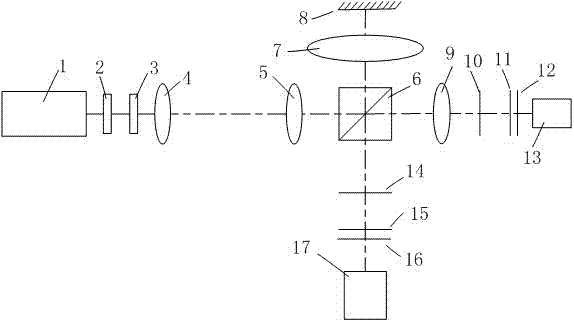
[0012] The working principle of the present invention: the light beam emitted by the laser light source passes through the polarizing plate and the λ / 4 wave plate, enters the microscopic objective lens and the collimating lens, and forms a parallel beam, which is divided into two beams by a beam splitter, one of which is The light beam is incident on the standard lens, the first grating and the second grating, and Moiré fringes are formed on the first frosted glass behind the second grating, and the first CCD collects the fringes and inputs them into the computer to calculate the angle α 1 , to get the focal length of the standard lens; the other light is incident on the long focal length lens to be measured, reflected by the mirror and incident on the third grating and the fourth grating, forming Moiré fringes on the second frosted glass, and the second CCD collects the fringes and inputs them into the computer Calculate fringe angle α 2 , to get the focal length of the long ...


PUM


Abstract

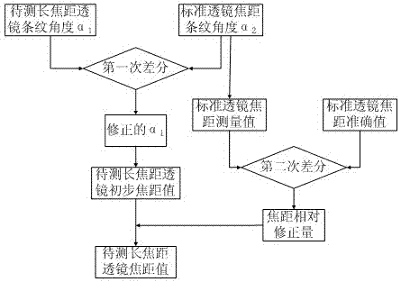
The invention discloses a compound differential type long-focus measuring device based on a Talbot effect. The light of a laser source runs through a polaroid, a lambda / 4 wave plate, a microscope objective and a collimating mirror, to be divided into two beams by a beam splitter prism, wherein one beam is incident to a standard lens, a first grating and a second grating, to form moire fringes on first ground glass, the first CCD (Charge Coupled Device) is used for collecting the fringes and inputting the fringes to a computer so as to calculate the angle alpha 1 of the fringes, to get a standard lens focus; the other beam is incident to a long-focus lens to be measured, reflected by a reflector and then incident to third and fourth gratings, to form moire fringes on second ground glass, and a second CCD is used for collecting the fringes and inputting the fringes to the computer so as to calculate the angle alpha 2 of the fringes; the alpha 1 and alpha 2 are subjected to differential treatment and the alpha 1 is corrected to obtain a long-focus value; and the standard lens focus and the known standard value thereof are subjected to differential treatment and the long-focus value to be measured is corrected to obtain a focus value of the long-focus lens to be measured finally. According to the device disclosed by the invention, the external interference is eliminated by adopting the two differential treatments, and the high precision measurement for the long-focus lens can be realized.

Description

technical field [0001] The invention belongs to the field of optical testing, in particular to a compound differential long focal length measuring device based on the Taber effect. Background technique [0002] In the fields of optics, astronomy and military affairs, the long focal length lens is a very critical basic component, playing an increasingly important role, and the required focal length is getting larger and larger, and the aperture is also getting larger. In large systems, such as the National Ignition Facility, long focal length lenses are the key light-gathering elements. The use of long focal length lenses requires corresponding detection technology, but there are still many difficulties in high-precision detection, especially the measurement accurate to several millimeters or even hundreds of microns. At present, there are many focal length measurement technologies. For example, a spherometer can accurately measure to 2 meters, with an accuracy of one ten-th...

Claims


Application Information

Patent Timeline
Patent Type & Authority Applications(China)
IPC IPC(8): G01M11/02
Inventor 金晓荣白剑侯昌伦
Owner ZHEJIANG UNIV
Learn More