System for measuring loss of optical resonant cavity based on optical cavity ring-down method

An optical resonant cavity and measurement system technology, applied in the field of measurement, can solve problems such as low efficiency and inconvenience, and achieve the effects of reducing cross-coupling, improving measurement accuracy, and improving coupling efficiency

Active Publication Date: 2011-11-23
XIDIAN UNIV
View PDF4 Cites 20 Cited by
  • Summary
  • Abstract
  • Description
  • Claims
  • Application Information

AI Technical Summary

Problems solved by technology

This method achieves high measurement accuracy in the case of low loss, but the common disadvantage is that it can only measure the loss of a certain eigenmode of the optical resonator, and the optical resonator often has a fundamental mode and numerous higher-order modes, the loss of these modes is very important for evaluating the performance of optical resonators
In order to measure the loss of all modes of the optical resonator, the measurement system must be greatly modified and multiple measurements are required, which is extremely inconvenient and inefficient

Method used


Image

  • System for measuring loss of optical resonant cavity based on optical cavity ring-down method
  • System for measuring loss of optical resonant cavity based on optical cavity ring-down method
  • System for measuring loss of optical resonant cavity based on optical cavity ring-down method

Examples


Embodiment Construction

[0027] The system structure of the present invention will be described in detail below in conjunction with the accompanying drawings.

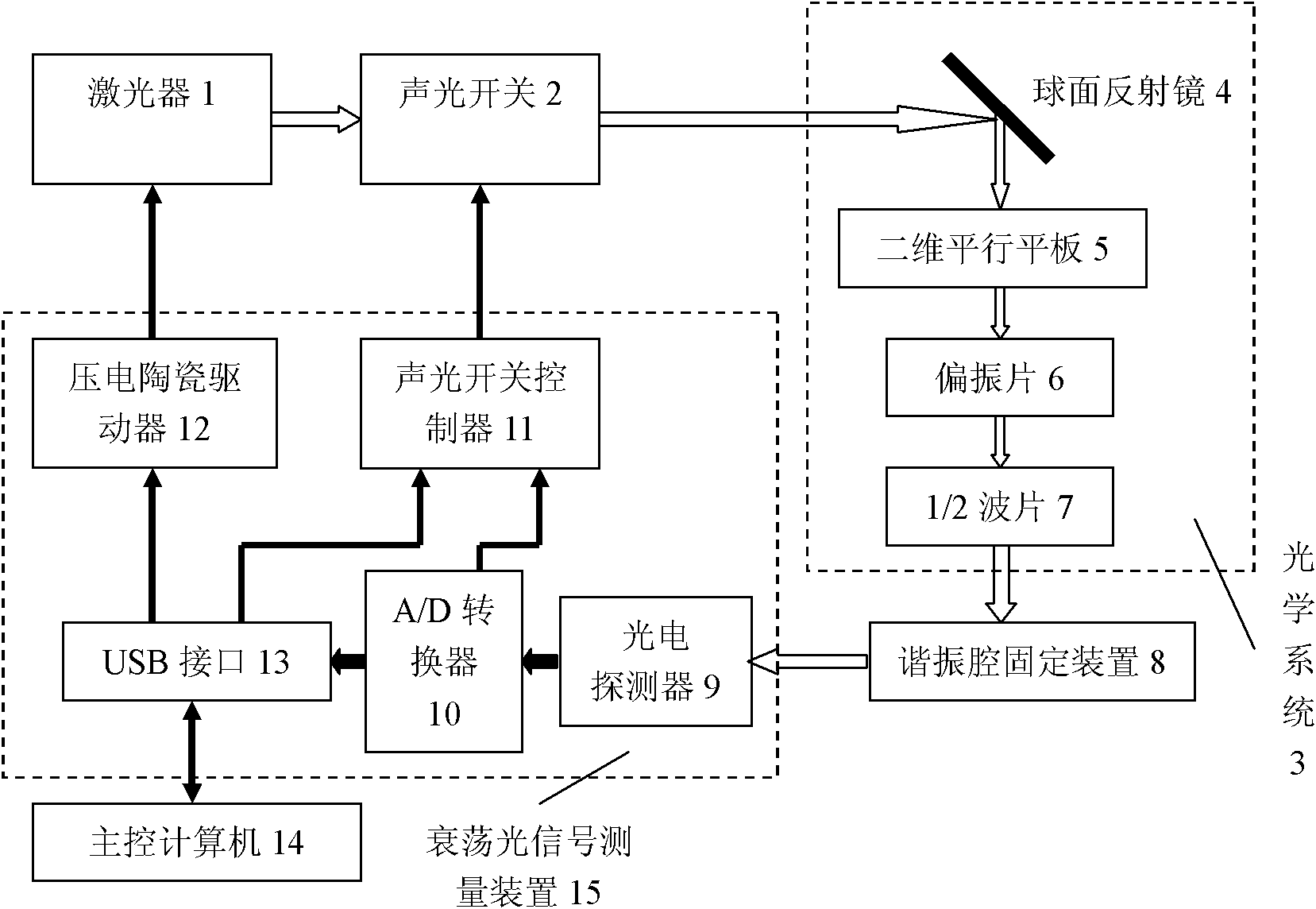
[0028] refer to figure 1 , The measurement system of the present invention includes a laser 1 , an acousto-optic switch 2 , an optical system 3 , a resonant cavity fixing device 8 , a ring-down optical signal measuring device 15 and a main control computer 14 . in:

[0029] Laser 1 is a single-mode frequency-sweeping laser with piezoelectric ceramics attached to it. By controlling the piezoelectric ceramics, the frequency of laser output from laser 1 can be adjusted. The laser output from the laser is transmitted to the acousto-optic switch 2 at the rear end of laser 1.

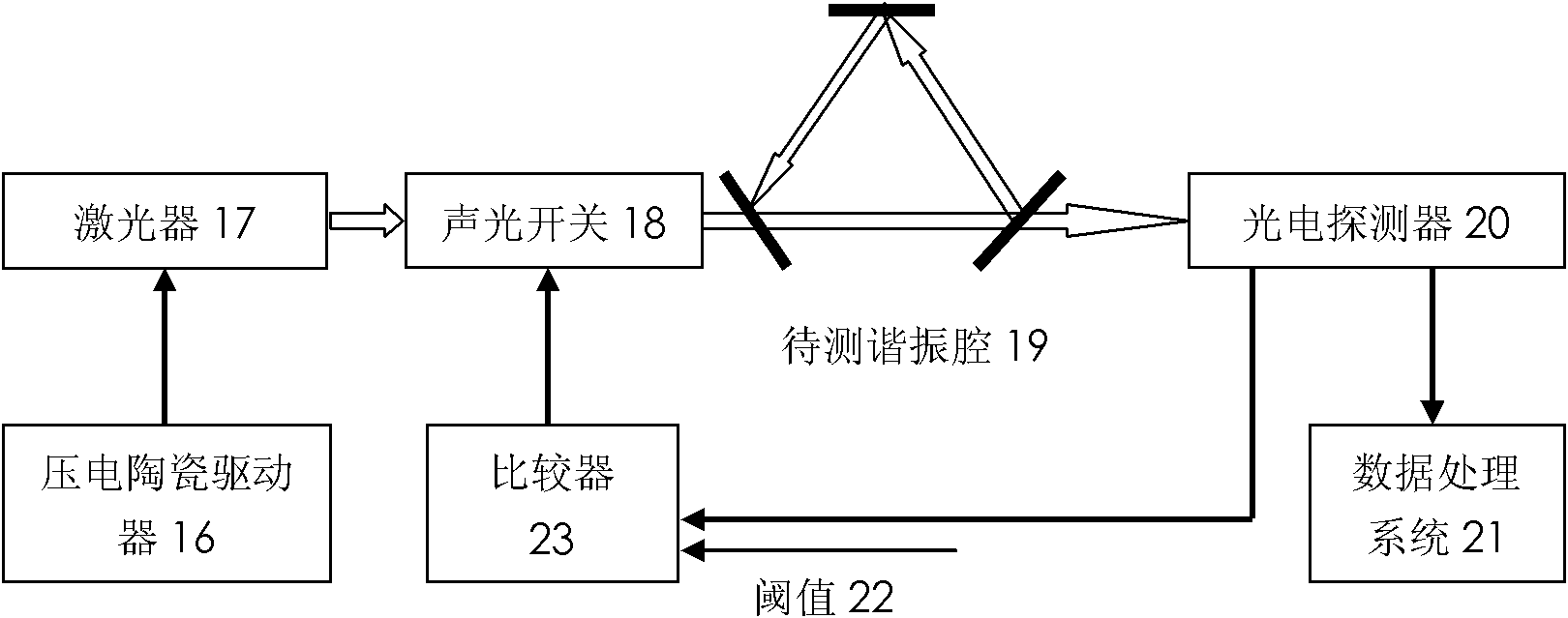
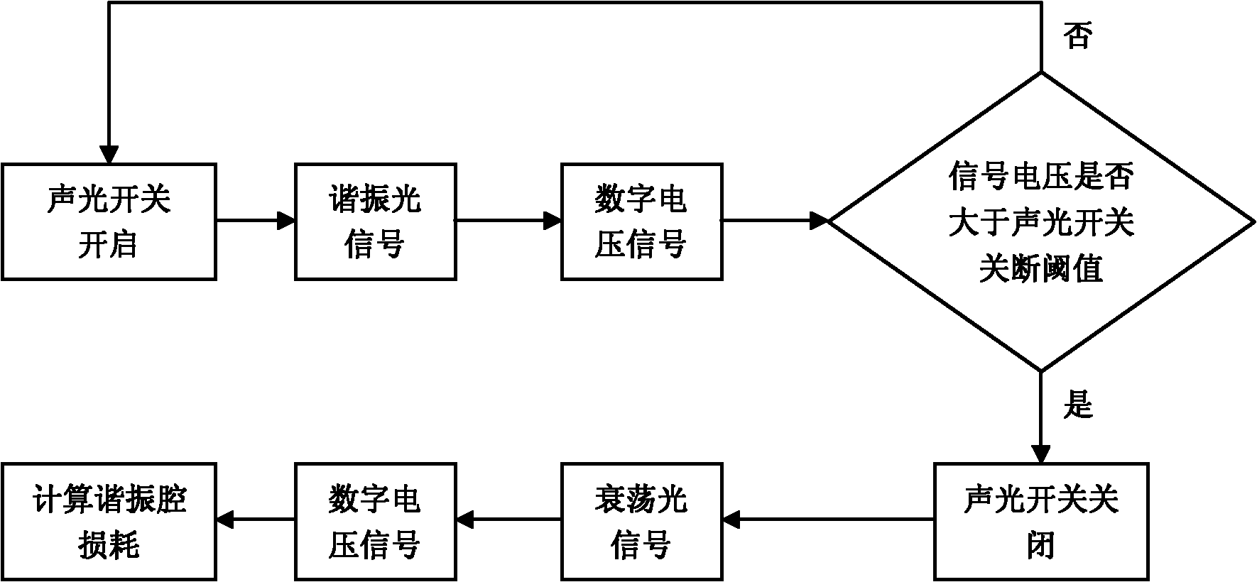
[0030] The acousto-optic switch 2 , under the control of the acousto-optic switch controller 11 , rapidly cuts off the multiple modes of laser light output by the laser 1 successively.

[0031] The optical system 3 is located behind the acousto-optic switch 2, which include...


PUM


Abstract

The invention discloses a system for measuring loss of an optical resonant cavity based on an optical cavity ring-down method and mainly overcomes the defect that the conventional system cannot measure the loss of a ground mode and a high-order mode simultaneously. The whole measurement system comprises a laser (1), an acousto-optic switch (2), an optical system (3), a resonant cavity fixing device (8), a ring-down light signal measurement device (15) and a main control computer (14); the laser sends a laser beam which enters the resonant cavity to be measured through the acousto-optic switchand the optical system to form resonant light; when the light intensity of the resonant light is greater than the preset turn-off threshold value of the acousto-optic switch, the acousto-optic switchis turned off to ensure that the resonant cavity to be measured generates ring-down light in a plurality of modes; the ring-down light is subjected to photoelectric conversion and analog-to-digital conversion and then is transmitted to the main control computer; and the main control computer fits and calculates the acquired data so as to obtain the loss of a plurality of laser modes. The system has the advantage of measuring the loss of the plurality of laser modes of the optical resonant cavity simultaneously and is suitable for high-efficiency measurement of the loss of the optical resonantcavity.

Description

technical field [0001] The invention belongs to the field of measurement technology, and in particular relates to a measurement system of an optical resonant cavity, which is mainly used for measuring the loss of the optical resonant cavity. Background technique [0002] At present, there are many methods for measuring the loss of optical resonators, such as: direct measurement method based on DF transflectometer, spectrum method based on measuring the free spectral range of optical resonator, and optical cavity based on measuring the decay time constant of optical resonator ring down method. The direct measurement method using DF transflectometer is simple, but it is only suitable for high loss measurement and the situation where the measurement accuracy is not high; the spectrum method based on the measurement of the free spectral range of the optical resonator, because the smaller the loss value is, the more difficult the measurement is. Therefore, it is only suitable fo...

Claims


Application Information

Patent Timeline
Patent Type & Authority Applications(China)
IPC IPC(8): G01M11/02
Inventor 邵晓鹏钟宬王杨陈少冲龚昌妹张崇辉侯谨妍杨晓晖
Owner XIDIAN UNIV
Why Eureka
Try Eureka