Wavelength drift compensation method for laser gas analyzer

A technology of laser gas and wavelength drift, which is applied in the direction of material analysis, analysis materials, and instruments by optical means, and can solve the problems of center wavelength shift of DFB lasers.

Inactive Publication Date: 2011-11-23
ANHUI WAYEE SCI & TECH CO LTD
View PDF4 Cites 16 Cited by
  • Summary
  • Abstract
  • Description
  • Claims
  • Application Information

AI Technical Summary

Problems solved by technology

[0007] The purpose of the present invention is to provide a wavelength drift compensation method for laser gas analyzers, which can compensate for the center wavelength shift

Method used


Image

  • Wavelength drift compensation method for laser gas analyzer
  • Wavelength drift compensation method for laser gas analyzer
  • Wavelength drift compensation method for laser gas analyzer

Examples


Embodiment Construction

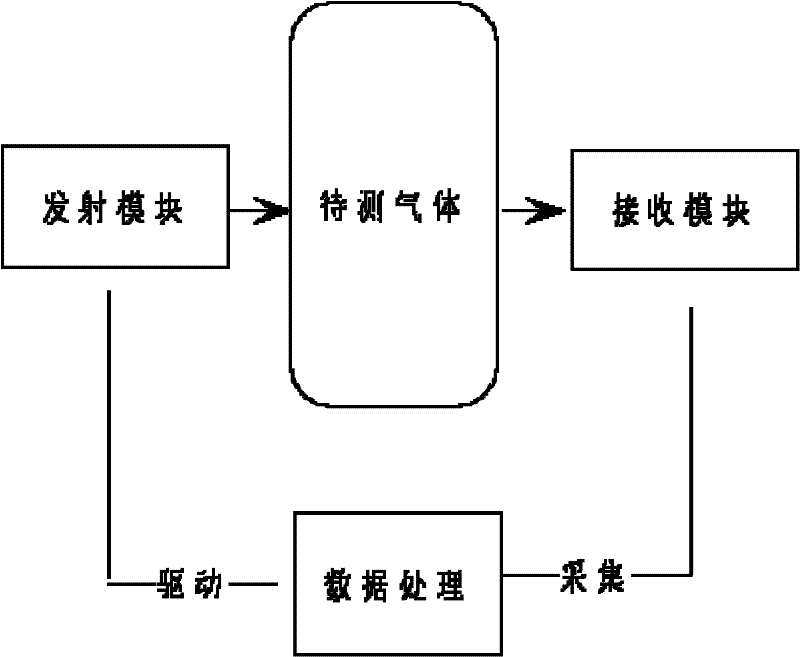
[0017] Such as figure 1 shown. The laser gas analyzer mainly consists of a laser emission module, a signal acquisition module and a central control and digital processing module. Both the transmitting module and the receiving module of the semiconductor laser gas analyzer are fixed on the industrial monitoring site through flange fixing, so it is difficult to disassemble and calibrate. Generally, it will be disassembled and calibrated once every six months or so. However, the center wavelength of the DFB laser will drift with the increase of continuous working time. If the DFB laser center wavelength drift compensation technology is not used, the position of the absorption peak will change with time, which will bring difficulties to the later signal processing. In severe cases, the output The result will be wrong.

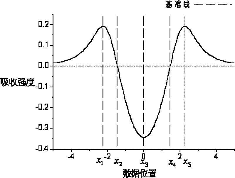
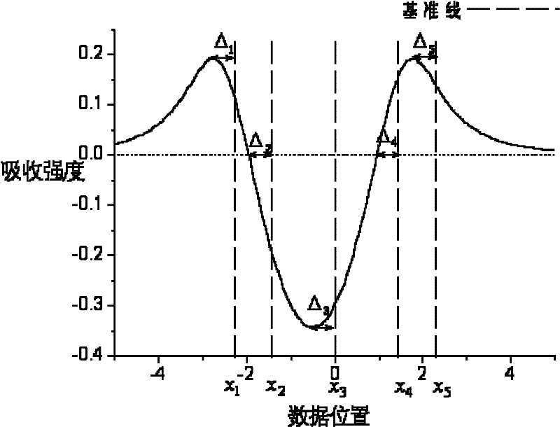
[0018] Such as figure 2 shown. From figure 2 It can be seen from the figure that the second harmonic signal collected by the laser gas analyzer through the...


PUM


Abstract

The invention discloses a wavelength drift compensation method for a laser gas analyzer. The wavelength drift compensation method for the laser gas analyzer is mainly used for compensating the central wavelength drift of a distributed feedback laser (DFB). In the method, the absorption peak position of a signal to be tested is detected and the absorption peak offset is fed back to a laser temperature control module, so that the central wavelength drift of the laser can be compensated. A multi-characteristic-point measurement method is adopted, so that the deviation of noises such as optical interference fringes and the like from the monitoring of the laser central wavelength offset can be reduced, the offset of the laser central wavelength can be measured precisely, and the whole system is credible.

Description

Background technique [0001] The invention relates to the field of laser gas analyzers, in particular to a wavelength drift compensation method for laser gas analyzers. Background technique [0002] The semiconductor (DFB) laser gas analyzer is a "real-time" and "on-line" gas monitoring device, which is often used in petrochemical, steel, cement, environmental protection, industrial online monitoring and other fields. Laser gas analyzer is a high-sensitivity gas analysis method. Its principle is that after the laser of a specific wavelength passes through the gas, it is absorbed by the specific absorption peak of the gas, resulting in attenuation of light intensity. The attenuation of light intensity can be accurately described by the Beer-Lambert law: [0003] [0004] in are the light intensity after the laser passes through the gas and before passing through the gas, v is the frequency of the laser, P, X and L are the pressure, concentration and optical path of the g...

Claims


Application Information

Patent Timeline
IPC IPC(8): G01N21/31G01N21/01
Inventor 阎杰
Owner ANHUI WAYEE SCI & TECH CO LTD
Why Eureka
Try Eureka