Phase difference synchronous measuring device and method for multi-way sine wave signals

A technology for synchronous measurement and measuring devices, which is applied to measuring devices, phase angles between voltage and current, and measuring electrical variables, etc. It can solve the problems of difficult phase measurement, large jitter fluctuations, and large zero-crossing distortion, etc., to achieve Avoid sampling clock jitter, good multi-channel phase synchronization, and high phase resolution

Inactive Publication Date: 2011-11-23
BEIJING CHANGCHENG INST OF METROLOGY & MEASUREMENT AVIATION IND CORP OF CHINA
View PDF0 Cites 20 Cited by
  • Summary
  • Abstract
  • Description
  • Claims
  • Application Information

AI Technical Summary

Problems solved by technology

It has always been a difficult problem to measure the phase difference of multi-channel sine wave signals synchronously with high precision. The main problem is that the measurement accuracy is affected by the delay, noise, time base distortion, time base jitter, time drift, trigger noise, trigger jitter, sampling Influenced by many factors such as spacing and waveform distortion, it is not easy to achieve high-precision measurement, and it is also difficult to obtain high phase measurement resolution
[0003] Most of the existing phase measurement technologies are based on the principle of zero-crossing detection. The phase difference is calculated by the ratio of the time difference between the zero-cross

Method used


Image

  • Phase difference synchronous measuring device and method for multi-way sine wave signals
  • Phase difference synchronous measuring device and method for multi-way sine wave signals
  • Phase difference synchronous measuring device and method for multi-way sine wave signals

Examples


Embodiment

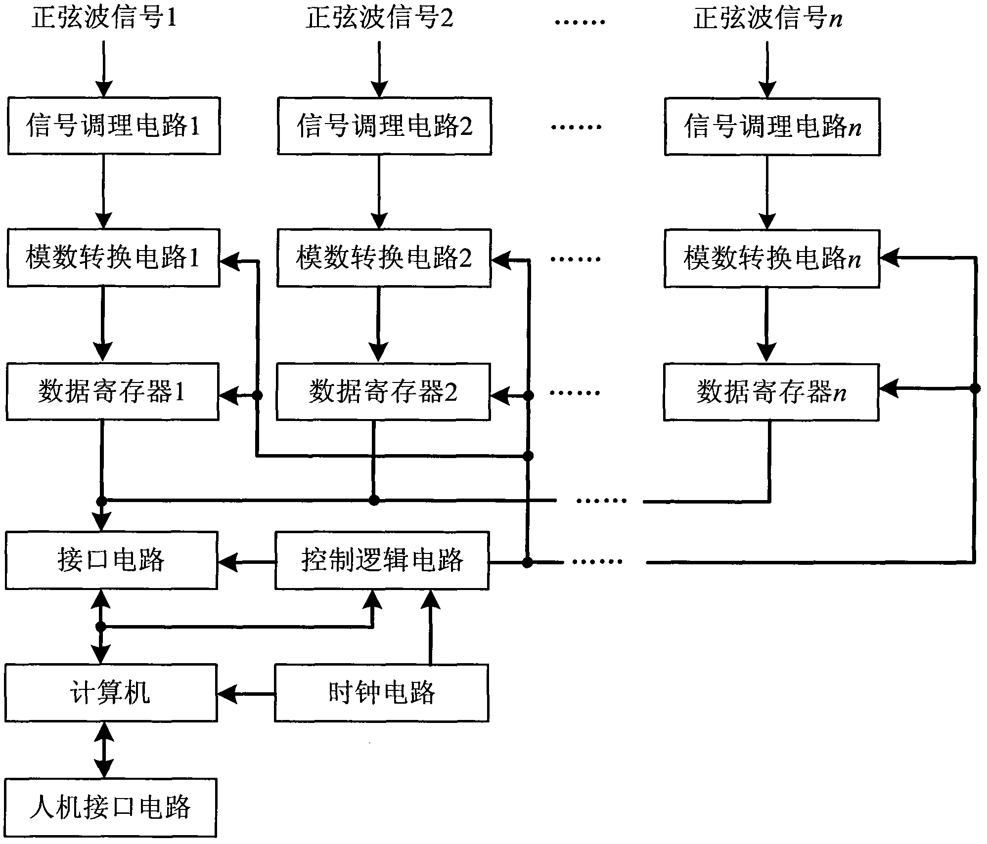
[0035] A phase difference synchronous measurement device for multi-channel sine wave signals, its structure is as follows figure 1 As shown, it includes two or more signal conditioning circuits, two or more analog-to-digital conversion circuits, two or more data registers, and common logic control circuits, interface circuits, computers, human Machine interface circuit and clock circuit, the measured object is the phase difference between two or more than two sine wave signals; the number of signal conditioning circuit, analog-to-digital conversion circuit and data register is the same, and they are used in one-to-one correspondence;

[0036] Each sine wave signal enters a signal conditioning circuit respectively, the signal conditioning circuit filters and amplifies the measured sine wave signal, and then outputs the signal to the corresponding analog-to-digital conversion circuit, and the analog-to-digital conversion circuit synchronizes the signal waveform Sampling and anal...


PUM


Abstract

The invention relates to a phase difference synchronous measuring device and a phase difference synchronous measuring method for multi-way sine wave signals, and belongs to the technical field of electronic measurement. The device comprises two or more than two signal conditioning circuits, two or more than two analog-to-digital conversion circuits, two or more than two data registers, a sharing logic control circuit, an interface circuit, a computer, a man-machine interface circuit and a clock circuit, and a measured object is phase difference of two or more than two ways of sine wave signals, wherein the number of the signal conditioning circuits, the number of the analog-to-digital conversion circuits and the number of the data registers are the same, and the signal conditioning circuits, the analog-to-digital conversion circuits and the data registers are matched in a one-to-one mode. Due to the adoption of the device and the method, the phase difference of the multi-way sine wave signals can be measured synchronously, the phase resolution is high, a waveform is stable, the multi-way phase synchronism is high, and error influence factors such as sampling clock jitter, channel synchronization error, the stability of channel phase delay, amplitude noise and the like in the conventional phase measuring method are prevented.

Description

technical field [0001] The invention relates to a phase difference synchronous measurement device and method for multi-channel sine wave signals, belonging to the technical field of electronic measurement. Background technique [0002] Phase difference measurement and reproduction technology is one of the basic technologies in the fields of electronics, electromagnetism and radio measurement, which is of great significance and far-reaching influence. For example, the power factor in the AC electric energy measurement test needs to measure the phase difference between the two-phase or three-phase AC voltage and current to finally determine it. In fact, two channels (one voltage, one current) or six channels (three voltages, Three-way current) The phase difference between the sinusoidal signals. In addition, the time difference measurement in many occasions is obtained indirectly through the phase difference measurement, so the synchronous and accurate measurement of the phas...

Claims


Application Information

Patent Timeline
IPC IPC(8): G01R25/00
Inventor 梁志国朱振宇武腾飞张大鹏李华丰
Owner BEIJING CHANGCHENG INST OF METROLOGY & MEASUREMENT AVIATION IND CORP OF CHINA
Why Eureka
Try Eureka