Supercharge Your Innovation With Domain-Expert AI Agents!

Multifunctional control circuit with power-off protection function for cloth cutting machine

A control circuit and power-off protection technology, which is applied in the direction of circuit devices, electrical components, emergency power supply arrangements, etc., can solve problems such as easy to touch the controller, complicated operation, easy damage to the host and slide rails, etc.

Inactive Publication Date: 2011-11-23
郭先敏
View PDF0 Cites 0 Cited by
  • Summary
  • Abstract
  • Description
  • Claims
  • Application Information

AI Technical Summary

Problems solved by technology

For the controller of the original cloth cutting machine, (1) when the original controller is powered off, the remaining inertia of the moving motor cannot be controlled, and the cloth breaking host directly collides with the end cover of the slide rail, which is easy to damage the cloth breaking host and the slide rail. rail
(2) The original controller, because the controller needs to be in the range of operation, it is easy to touch the controller when the cloth and the slide rail are lifted, causing inconvenience
(3) In the application of the lifting frame of the original cloth cutting machine, two methods are adopted, automatic and manual. When encountering some fabric curling, it needs to be manually used to sweep the cloth manually, and then lower the slide rail to flatten the cloth. , manual is inefficient, and automatic lifting cannot effectively deal with the curling phenomenon
(4) The original controller needs to be pre-set or set before sharpening the knife, which makes the operation complicated and inconvenient to use

Method used


Image

  • Multifunctional control circuit with power-off protection function for cloth cutting machine
  • Multifunctional control circuit with power-off protection function for cloth cutting machine
  • Multifunctional control circuit with power-off protection function for cloth cutting machine

Examples


Embodiment Construction

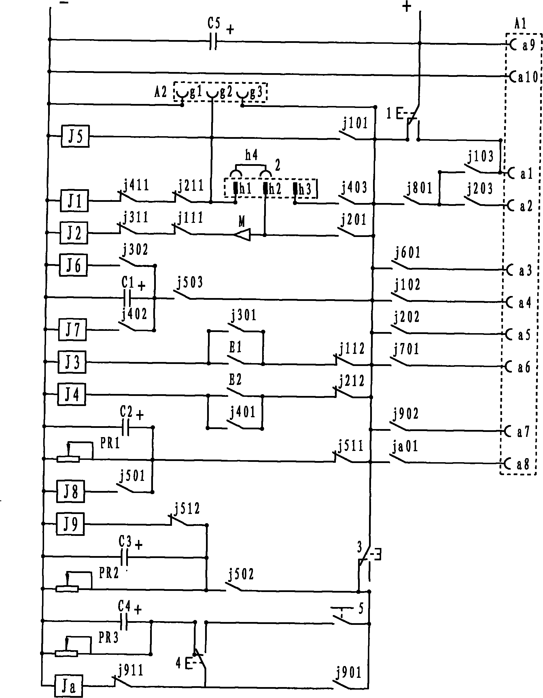
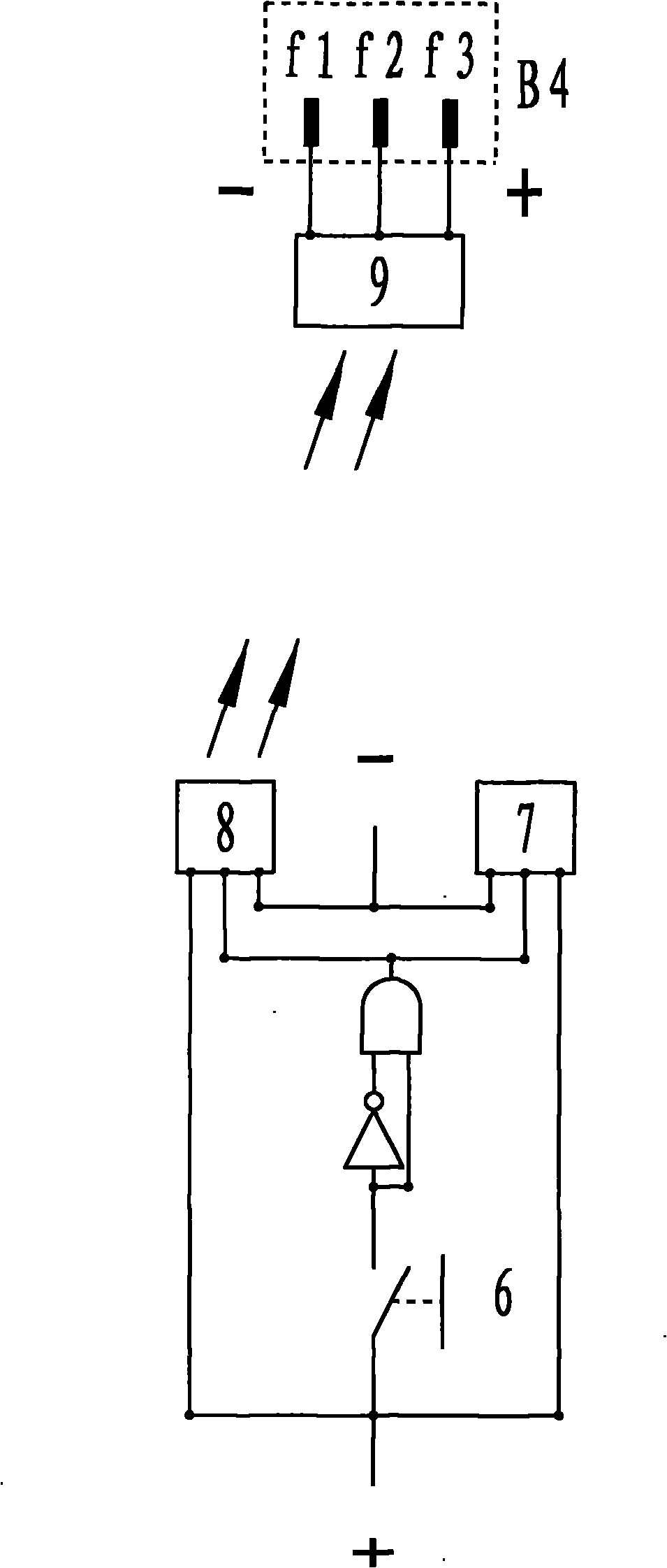
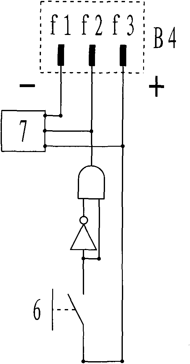
[0011] Please also see figure 1 , Figure 2A , Figure 2B and image 3 The power-off protection and multi-functional cloth cutting machine control circuit of the present invention, the control circuit takes the relay circuit as the core, adopts analog switch integration or logic integration to replace the relay, and the control circuit is respectively composed of relays (j1), (j2), (j3) , (j4), (j5), (j6), (j7), (j8), (j9), (ja), each relay switch, capacitor (C1), (C2), (C3), (C4), (C5), potentiometer (PR1), (PR2), (PR3), buffer (m), proximity switch (E1), proximity switch (E2), sharpening switch (1), conversion socket (2), lift Changeover switch (3), descending changeover switch (4), manual descending switch (5) form.

[0012] The relay switch is represented by the first two digits of the relay code, such as j1 represents the relay (j1), j2 represents the relay (j2), ja represents the relay (ja), the third digit 0 is a normally open switch, 1 is a normally closed switch, ...


PUM


Abstract

The invention relates to a control circuit of a cloth cutting machine, wherein a relay circuit is used as a core; an analog switch assembly or a logic assembly is adopted to replace relays; a larger-capacity capacitor is arranged at a power supply input position and is used for ensuring that the control circuit continuously works within a short time during power interruption; a starting socket can be in plugging connection with a receiver for a wireless purpose and is started by a remote controller, or the starting socket can also be in direct plugging connection with a starting switch and a counter for usage; after a magnetic switch is in contact with a magnetic block, the circuit is self-locked so that the cloth cutting machine can be prevented from vibration and displacement during lifting and the circuit can be prevented from judging directions falsely; a convertible transmission motor works in a one-way transmission manner and a two-way transmission manner; during cutter sharpening, the control circuit is cut off, a main motor is started independently and can be in plugging connection with the driving circuits of different motors or with a remote controller, and the remote controller is used for controlling the motor driving circuit provided with the receiver; and the control circuit has manual, semi-automatic and full-automatic lifting functions.

Description

technical field [0001] The present invention relates to a controller, in particular to a control circuit of a cloth cutting machine. Background technique [0002] The cloth cutting machine is a machine installed on the cutting bed to cut the cloth. The cloth cutting machine is composed of a cloth cutting machine, a slide rail and two lifting frames. On the slide rail seat of the lifting frame, the cloth cutting machine is placed in the slide rail, the cloth is pulled to the required length through the upper end of the slide rail, the cloth cutting machine cuts off the cloth, and then lifts the lifting frame to press the cut cloth on the slide rail Below, the cut cloth is repeatedly pressed under the slide rail so that the cut cloth is flattened. The cloth cutting machine is divided into manual and fully automatic, including one-way cutting and two-way cutting. Manually install the start switch on the handle of the cloth cutting main machine to start the main motor. After st...

Claims


Application Information

Patent Timeline
IPC IPC(8): H02J9/00D06H7/00
Inventor 郭先敏
Owner 郭先敏
Features
  • R&D
  • Intellectual Property
  • Life Sciences
  • Materials
  • Tech Scout
  • Unparalleled Data Quality
  • Higher Quality Content
  • 60% Fewer Hallucinations
Learn More