Magnetic generator

A generator and magnetic technology, applied in the directions of generators/motors, electrical components, etc., can solve the problems of high power transmission cost, large loss of raw materials, low power factor, etc., and achieve light weight, reduced loss, and improved power factor. Effect

Inactive Publication Date: 2011-11-23
黄扬芳
View PDF0 Cites 0 Cited by
  • Summary
  • Abstract
  • Description
  • Claims
  • Application Information

AI Technical Summary

Problems solved by technology

Furthermore, due to various reasons, this type of generator has "five big and one small" problems, that is, large material loss, lar

Method used


Image

  • Magnetic generator
  • Magnetic generator
  • Magnetic generator

Examples


Embodiment Construction

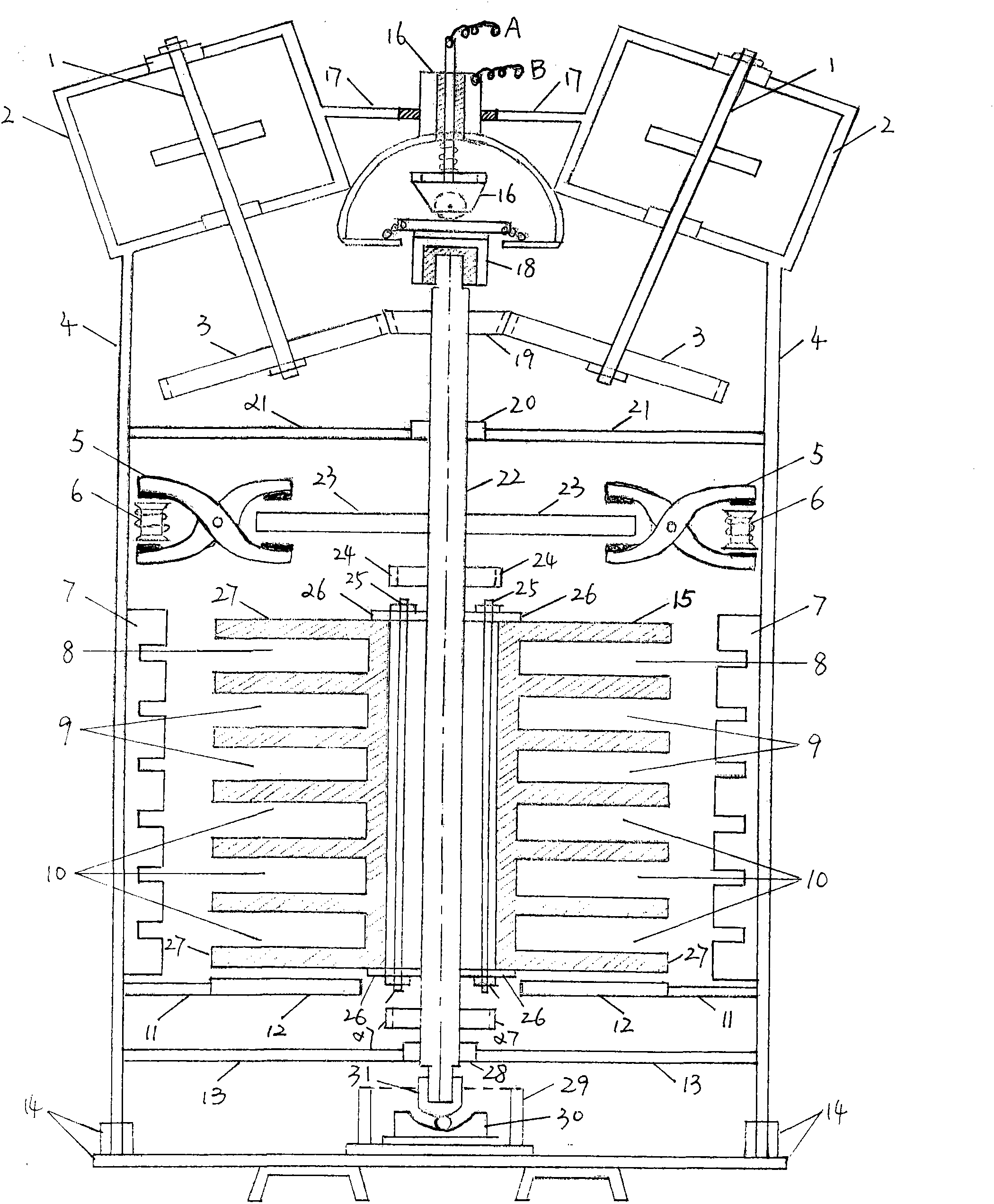
[0064] (1) The name, function and installation of the main components of the whole machine (except the stator). (See figure 1 )

[0065]Magnet assembly 1, also known as magnet, has the function of applying force to the rotor shaft 22, and it is fixed on the frame 4. Magnet support 2, effect: fix magnet 1 position, guarantee that magnet drive wheel 3 and rotor shaft are equipped with drive wheel 19 two gears and effectively match, and it is installed on the frame 4. The magnet drive wheel 3 has an effect: the magnet rotating power is passed to the rotating shaft 22, and it is installed on the magnet rotating shaft 44. Frame 4, effect: fixed support 17,21,13 and device make complete machine run smoothly, and it is firmly combined with base plate and base plate foot 14. Brake 5, effect: can automatically or manually brake or release brake to rotor shaft 22, and it is installed on the frame 4. Brake control coil 6, function: control the working state of brake 5, it is installe...


PUM


Abstract

The invention discloses a magnetic generator. The technical scheme adopted by the invention is as follows: a part of induced electromotive force of the generator is directly converted to a rotating dynamic force of the generator along with the generator, one part of a U-shaped multilayer permanent magnet is a generating system rotor, the other part of the U-shaped multiplayer permanent magnet is a driving system rotor, the generating system rotor and the driving system rotor are installed on a rotating shaft and are connected with a bearing of the rotating shaft; the U-shaped multilayer permanent magnet is a common magnetic field body for the generating and outputting system and a power driven system; and two to five magnetic device assemblies are arranged above the rotating shaft, and twelve magnetic devices are arranged in each magnetic device assembly. According to the generating structure and the design of the dynamic force required for the generation in the invention, the power factor can be greatly boosted compared with the power factor of the traditional generator, thus the problems of large raw materials consumption, large running resistance, large magnetic circuit loss, large internal eddy and high power transmission cost can be effectively solved. The magnetic generator disclosed by the invention does not depend on natural dynamic force, cannot consume lots of resources, is beneficial to environmental protection and has low noise, no pollution and low power transmission cost.

Description

technical field [0001] The invention relates to a generator. Background technique [0002] At present, all generators at home and abroad will consume a large amount of natural resources, or be limited by natural environmental conditions. Due to changes in the natural environment and large-scale depletion of its resources, natural resources will be depleted after a few centuries. Furthermore, due to various reasons, this type of generator has "five big and one small" problems, namely, large material loss, large running resistance, large magnetic circuit loss, large internal eddy current, high power transmission cost, and low power factor. So humans should look for new ways. Contents of the invention [0003] The purpose of the present invention is to develop a magnetic generator that does not need to consume a large amount of resources, has no pollution, and has low power transmission costs. [0004] The technical scheme that the present invention takes is: [0005] A p...

Claims


Application Information

Patent Timeline
IPC IPC(8): H02N11/00H02K57/00
Inventor 黄扬芳
Owner 黄扬芳
Why Eureka
Try Eureka