Control method of heat capillary flow in liquid drop

A thermal capillary flow and droplet technology, applied in the field of micro-electromechanical systems, can solve the problems of long temperature response time, low control accuracy, weak thermal capillary flow, etc., and achieve simple and convenient operation, sensitive and rapid control, and shortened response time Effect

Active Publication Date: 2013-05-29
SHANGHAI JIAOTONG UNIV
View PDF3 Cites 0 Cited by
  • Summary
  • Abstract
  • Description
  • Claims
  • Application Information

AI Technical Summary

Problems solved by technology

However, in the plate-based heating method, the contact surface between the droplet and the plate is heated as a whole, and the size of the droplet in practical applications is usually in the order of millimeters and microns. , the droplet temperature difference is not obvious, and the temperature gradient of the droplet is very small, so the thermal capillary flow generated inside the droplet is also very weak, which means that the controllable range of the thermal capillary flow inside the droplet is not wide by means of plate heating. The accuracy is not high
At the same time, because the heating method of the flat plate needs to maintain a stable temperature of the entire substrate, the temperature response time will be longer and the adjustment process will be more complicated.

Method used


Image

  • Control method of heat capillary flow in liquid drop
  • Control method of heat capillary flow in liquid drop
  • Control method of heat capillary flow in liquid drop

Examples


Embodiment

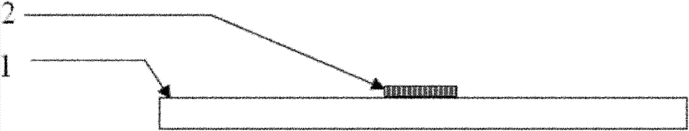
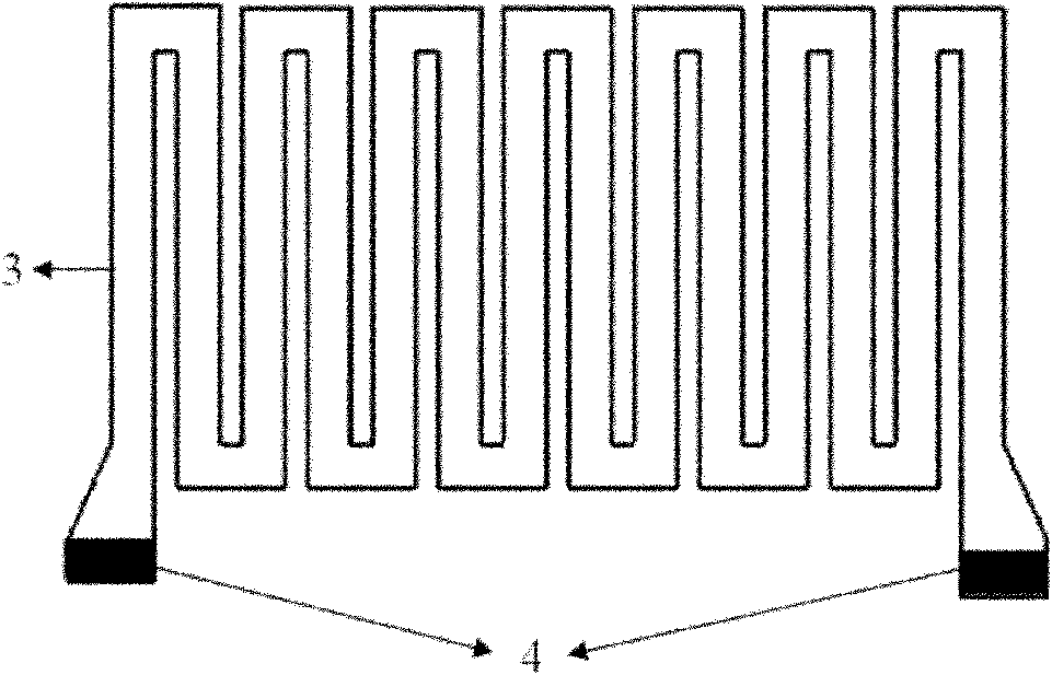
[0022] Step 1, refer to figure 1 As shown, the integrated micro heater 2 is processed on the substrate 1 by micro-electro-mechanical technology. The structure of the micro heater is as figure 2 As shown, it is composed of a heating wire part 3 and a lead wire part 4, and the end of the heating wire is connected with the lead wire part. The heating wire part 3 of the micro heater is composed of 20nm titanium and 200nm platinum, and its shape is meandering, with a coverage area of ​​200 μm (width)×410 μm (length), a line width of 20 μm, and a line spacing of 10 μm. The lead part 4 of the micro-heater is composed of 100nm gold compounded on the basis of the heating wire 3, and the line width is 20 μm.

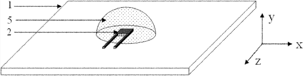
[0023] Step 2, after cleaning the surface of the substrate including the surface of the micro-heater, place the droplet 5 on the heating wire 2 of the micro-heater, such as image 3 As shown, the heating wire 3 of the micro heater is located at the center of the contact surfac...


PUM


Abstract

The invention relates to a control method of a heat capillary flow in a liquid drop in the field of an MEMS (Micro Electro Mechanical System) technique. The method provided by the invention comprises the following steps: machining a miniature heater on a substrate by utilizing the MEMS technique, wherein the dimension of the miniature heater is in a micrometer level and the area partially covered by a heating filament is less than that of the contact surface of the liquid drop with the substrate; then placing the liquid drop at the upper part of the miniature heater and applying voltages at the two ends of the miniature heater; enabling the heating filament of the miniature heater to generate heat and partially heats the bottom of the liquid drop; and generating a temperature gradient in the liquid drop, thereby causing the heat capillary flow flowing of the fluid in the liquid drop and controlling the heat capillary flow in the liquid drop. The method provided by the invention can be used for rapidly and effectively adjusting the temperature of the miniature heater to control the temperature distribution of the liquid drop, thereby controlling the heat capillary flow in the liquid drop and enhancing the controllable range of the heat capillary flow.

Description

technical field [0001] The invention relates to a method in the technical field of micro-electromechanical systems, in particular to a method for controlling thermal capillary flow inside a droplet. Background technique [0002] After the droplets containing solutes or particles are evaporated to dryness, the solutes or particles will be deposited on the surface of the fixation where the droplets are located, forming a certain deposition pattern. In the early 1990s, Deegan et al. found that when the liquid droplets fixed on the plate were heated at the bottom, the thermal capillary flow inside the liquid droplets was the main reason for the formation of ring-shaped deposition patterns after the liquid droplets evaporated, which also explained The famous "coffee ring" phenomenon. The evaporative deposition technology of droplets has many important applications in the fields of biomedicine and materials, such as DNA / RNA sequence analysis, drug delivery, and the manufacture of...

Claims


Application Information

Patent Timeline
Patent Type & Authority Patents(China)
IPC IPC(8): B01D1/22H05B3/20H05B3/02
Inventor 胡定华吴慧英吴信宇陈娅琪
Owner SHANGHAI JIAOTONG UNIV
Why Eureka
Try Eureka